Download
1 / 33
330 likes | 343 Views
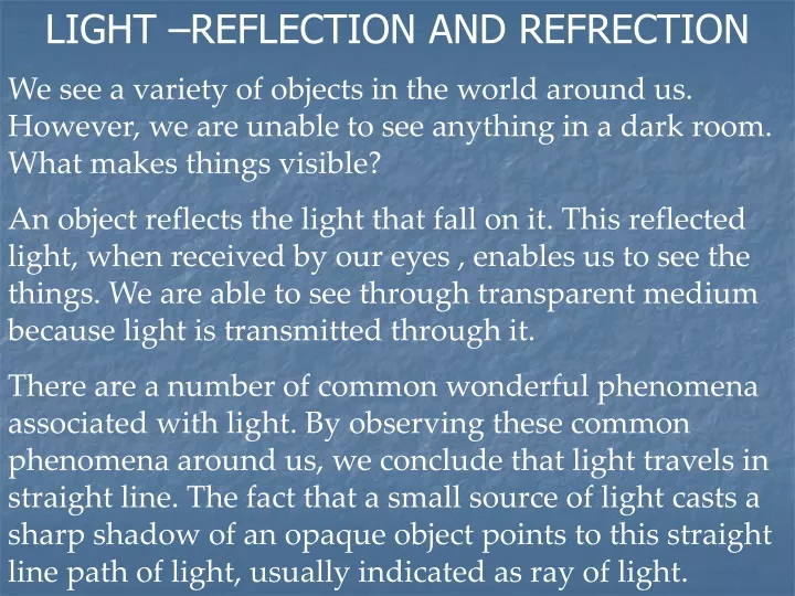
LIGHT –REFLECTION AND REFRECTION We see a variety of objects in the world around us. However, we are unable to see anything in a dark room. What makes things visible?

E N D
LIGHT –REFLECTION AND REFRECTION We see a variety of objects in the world around us. However, we are unable to see anything in a dark room. What makes things visible? An object reflects the light that fall on it. This reflected light, when received by our eyes , enables us to see the things. We are able to see through transparent medium because light is transmitted through it. There are a number of common wonderful phenomena associated with light. By observing these common phenomena around us, we conclude that light travels in straight line. The fact that a small source of light casts a sharp shadow of an opaque object points to this straight line path of light, usually indicated as ray of light.
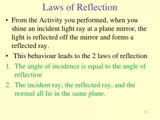
Reflection of Light:A highly polishedsurface, such as a mirror, reflects most of the light falling on it. Light is reflected by polished surfaces following some universal laws. Let us recall those laws--- • The angle of incidence is equal to the angle of reflection. • The incident ray, the normal to the mirror at the point of incidence and the reflected ray, all lie in the same plane. These laws of reflection are applicable to all types of reflecting surfaces including spherical surfaces.
SPHERICAL MIRRORS (Note: Click the highlighted words to see figure) The reflecting surface of a spherical mirror may be curved inwards or outwards. A spherical mirror, whose reflecting surface is curved inwards, is called a concave mirror. A spherical mirror whose reflecting surface is curved outward, is called convex mirror. Now, let us understand the meanings of some other related terms. 1. The centre of the reflecting surface of a spherical mirror is a point called the pole, usually represented by the letter P. 2. The reflecting surface of a spherical mirror forms a part of sphere. The sphere has a centre. This point is called the curvature of the spherical mirrorand represented by C. 3. The radius of the sphere is called the radius of curvatureof the mirror and represented by R. 4. Consider an imaginary line through the centre of curvature and the pole, which is called the principal axis. 5. The principal axis is the normal to the mirrorat its pole.
Concave mirror Convex Mirror Back to previous slide
6. A number of rays parallel to the principal axis are falling on concave mirror. They intersect at a point on the principal axis after reflection. This point is called the principal focus of the concave mirror. 7. Similarly, the rays parallel to the principal axis on a convex mirror, after reflection, seems to come from a point on the principal axis. This point is called the principal focus of the convex mirror. 8. The principal focus is represented by the letter F. The distance between the pole and the principal focus of spherical mirror is called the focal length, represented by f . 9. The diameter of the reflecting surface of a spherical mirror is called the aperture. The distance MN in the figure is the aperture. 10. There is a relationship between R and f, of a spherical mirror, given by R= 2 f .
Image formation by Spherical Mirrors. Light (AM) falling on a concave mirror at an angle θ to the normal is reflected at the same angle to pass through F, the principal focus. The centre of curvature of the mirror is C. For small angles, CP (radius, r) is twice the length of FP (focal length, f ). The pole, or centre, of the mirror is P. In convex mirrors, the principal focus, F, is the point from which rays striking the mirror parallel to the principal axis appear to come after reflection. The focal length, f, has a negative value.
Representation of Images formed by Spherical Mirrors Using Ray Diagrams. Formation of images by spherical mirrors by can be studied by drawing Ray-Diagrams. The following steps narrates how to draw ray diagrams. Consider an extended object, of finite size, placed in front of a spherical mirror. An infinite number of rays originated from each point of the object (point source of ray), which will be reflected back by the mirror. To construct ray diagram, consider only two convenient rays, whose directions after reflection from the mirror is easily known. The intersection of at least two reflected rays give the position of image of the point object. The figures in the next two slide shows some of such suitable rays .
Image formation by Concave Mirror. The following figures show the ray diagrams for the formation of image by a concave mirror for various positions of the object.
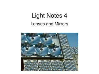
Use of concave Mirrors Concave mirrors are commonly used in Torches, search- lights and vehicles headlights to get powerful parallel beams of light. They are often used as shaving mirrors to see large image of the face. The dentist use concave mirrors to see large images of the teeth of patients. Large concave mirrors are used to concentrate sunlight to produce heat in solar furnaces.
Image formation by Convex Mirrors. We consider two positions of the object for studying the image formed by a convex mirror. First is when the object is at infinity and the second position is when the object is at finite distance from the mirror. The ray diagrams for formation of image by a convex mirrors for these two positions of object are shown below.
Nature, position and relative size of the image formed by a convex mirror. Use of Convex Mirror: Convex mirrors are commonly used as rear-view (wing) mirrors in vehicles. These mirrors are fitted on the sides of the vehicles, enabling the driver to see traffic behind. Convex mirrors are preferred because they always give an erect, though diminished, image. Also, they have wider field of views as they are curved outwards.
Sign Convention for Reflection by Spherical Mirrors While dealing with the reflection of light by spherical mirrors, a new set of sign convention is used, called the New Cartesian Sign Convention. ( Click Here to view figure) In this convention, the (P) is is taken as the origin. The Principal axis is taken as the X- axis (X’ X) of the coordinate system. The conventions are as follows------- • The object is always placed to the left of the mirror. This implies that the light from the object falls on the mirror from the left hand side. • All distances parallel to the principal axis are measured from the pole of the mirror. • All distances measured to the right of the origin are taken as positive while those measured to the left of the origin are taken as negative. • Distances measured perpendicular to and above the principal axis are taken as positive. • Distances measured perpendicular to and below the principal axis are taken as negative.
New Cartesian Sign Convention for a spherical mirror Go Back
Mirror Formula In a spherical mirror, the distance of the object from its pole is called the object distance (u). The distance of the image from the pole of the mirror is called image distance (v). The distance of the principal focus from the pole is known as the focal length (f) . There is a relationship among these three quantities given by mirror formula which is expressed as— 1/v + 1/u = 1/f . This formula is valid is all situation for all spherical mirrors for all positions of the object. We have to use New Cartesian Sign convention while substituting Numeric values for u, v, f and R in mirror formula for solving problems.
Magnification A magnifying glass is a large convex lens commonly used to examine small objects. The lens bends incoming light so that an enlarged, virtual image of the object (in this case a mushroom) appears beyond it. The image is called virtual because the light rays that appear to come from it do not actually pass through it. A virtual image cannot be projected on a screen.
Magnification produced by a spherical mirror gives the relative extend to which the image of an object is magnified with respect to the object size. It is expressed as the ratio of the height of the image to the height of the object. If h is the height of the object and h’ is the height of the image, then the magnification m produced by a spherical mirror is given by m= h’ / h The magnification is also related to the object distance (u) and image distance (v). It can be expressed as: Magnification (m) = h’ / h = v/ u. Note: It is to be noted that the height of the object is taken to be positive as the object is usually placed above the principal axis. The height of the image should be taken as positive irtual image and as negative for real image.
Compound Microscope Two convex lenses are sufficient to make a microscope. Each converges the light rays that pass through it. One lens, called the object lens, is positioned close to the object to be viewed. It forms a magnified and inverted image. This is called a real image because the light rays actually pass through the place where the image lies. This image is viewed by the second lens, acting simply as a magnifying glass. This eyepiece lens is positioned so that it does not form a second real image, but it makes the light rays spread more, so that as they enter the observer’s eye they appear to come from a large inverted image beyond the object lens. Because light rays do not really pass through this location, the image is described as virtual.
Refraction of light Refraction, bending of waves that occurs when a wave front passes obliquely from one medium to another. The phenomenon is most familiar with light waves. When light passes from a less dense medium (for example, air) to a denser one (for example, glass), it is refracted towards the normal. This occurs because the light waves are slowed down by the denser medium, causing them to change direction. On passing from a denser medium into a less dense one, the light is refracted away from the normal.
Laws of Refraction. There are two laws of refraction: The incident ray, the refracted ray, and the normal all lie in the same plane. For light rays passing from one transparent medium to another, the sine of the angle of incidence, i, and the sine of the angle of refraction, r, bear a constant ratio to one another. This is most simply stated mathematically: sin i/sin r = a constant. This constant is usually given the symbol, n, and is called the refractive index of the material. The higher the refractive index,the greater will be the extent of the refraction. This law is known as Snell’s law.
Lateral Displacement of Light Light entering the glass block is refracted towards the normal, and on leaving the block is refracted away from the normal to exactly the same extent. The effect of this is that the emergent ray is parallel to the incident ray, but is “laterally displaced” from it.
Refraction of Light by a Prism Light entering a prism is refracted towards the normal, and the emerging ray is refracted away from the normal, turning the ray through a considerable angle. Because the refractive index of a substance varies for the different wavelengths, a prism can spread out the various wavelengths of light contained in an incident beam and form a spectrum.
Sunlight reflecting off a fish in water, for instance, changes to a higher speed and bends when it enters air. The light appears to originate from a place in the water above the fish’s actual position.
Refraction by Spherical Lenses A spherical lens, either convex lens or concave lens has two spherical surfaces. Each of these surfaces forms a part of a sphere. The center of these spheres are called centre of curvature represented by C1 and C2 respectively. An imaginary straight line passing through the two centers of curvatures is its principal axis. The central point of a lens is its optical center, O. The effective diameter of the circular outline of a spherical lens is called its aperture.