Download
1 / 31
310 likes | 319 Views
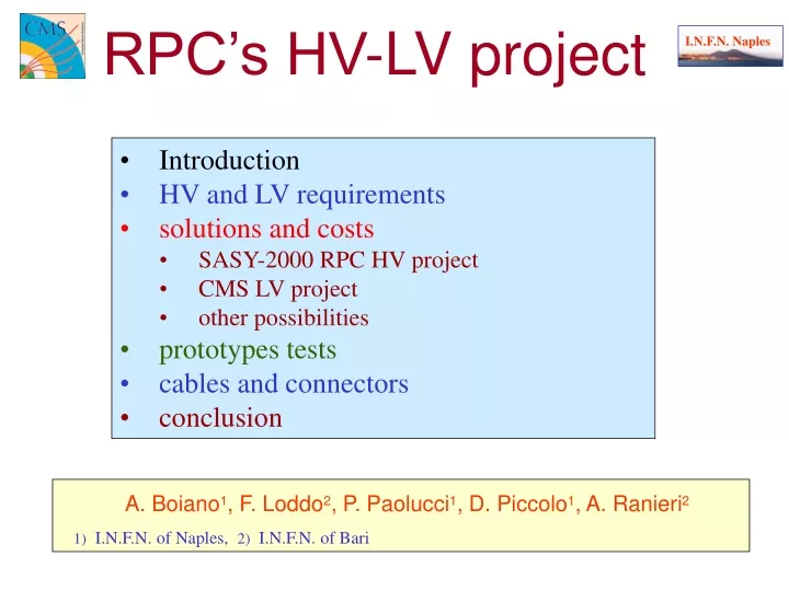
This article discusses the HV-LV system requirements, solutions, and costs for RPC detectors in LHC experiments. It focuses on the SASY-2000 RPC HV project, CMS LV project, and other possibilities. Prototype tests, cables, and connectors are also explored.

E N D
A. Boiano1, F. Loddo2, P. Paolucci1, D. Piccolo1, A. Ranieri2 1) I.N.F.N. of Naples, 2) I.N.F.N. of Bari RPC’s HV-LV project I.N.F.N. Naples • Introduction • HV and LV requirements • solutions and costs • SASY-2000 RPC HV project • CMS LV project • other possibilities • prototypes tests • cables and connectors • conclusion
Introduction I I.N.F.N. Naples • The RPCs sub-detectors of the LHC experiments will be for the first time equipped with a large part of the HV-LV system placed in a not accessible area. • The HV “remote hardware” will be placed on the balcony and it will be accessible just in some dedicated period. • The system will work in very hard conditions for the high magnetic field and high radiation environment. Pierluigi Paolucci - I.N.F.N. Naples
Introduction II I.N.F.N. Naples • Theidea of the HV-LV system for the RPC detector of the LHC experiments is to split the system in two: • LOCAL:SY1527 mainframes placed in control room and a 48 Volts High Power Source; • REMOTE:distribution system placed in the UXC zone around the detector. It consists of a 6U custom crate housing 2 independentcontrollers and up to 8 distribution board equipped with 4 HV + 8 LV floating channels. • The system will work in very hard conditions due to the high magnetic field and high radiation environment. • A common project (SASY 2000) to realize this system is going on between the I.N.F.N. and the CAEN company. Pierluigi Paolucci - I.N.F.N. Naples
RB3/RB4 RB2 reference plane RB1/RB2in Bigap Bigap Bigap Bigap Bigap Bigap Bigap Bigap ALV2 DLV2 ALV1 DLV1 Bigap HV1 HV2 HV1 HV2 ALV1,ALV2,ALV3 DLV1,DLV2,DLV3 detector description I I.N.F.N. Naples ALV1 DLV1 ALV2 DLV2 HV1 HV2 HV1 HV2 HV3 Two non adjacent gaps will be connected to the same HV channel in order to halve the # of HV channels “without” reducing the trigger efficiency. Pierluigi Paolucci - I.N.F.N. Naples
detector description II I.N.F.N. Naples RB1/RB2in RPC chamber Front-End Bigap Distrib. board Bigap ALV1 DLV1 ALV2 DLV2 ALV Analog Voltage = 7V Working Cur. = 0.42 A DLV DigitalVoltage = 7V WorkingCur. = 0.9 A I2C input LV+I2C FEB out LV in Distributes analog and digital LV It supplies LV power to 3 FEB chains It supplies the I2C main line from LB and one backup line from DT. Total power/(ALV+DLV) ch.:1.32 A * 7 V = 9.24 W Expected Power 120 W/sector 7.2 kW/Barrel Pierluigi Paolucci - I.N.F.N. Naples
requirements andnumbers I.N.F.N. Naples • requirements: • system working in high magnetic field; • system working in an high radiation environment; • local system in control room + distributed remote systems on the detector; • low voltage (48 Volts) running from the local to the remote system; • floating HV (12KV–1mA) and LV (7V–0.42A (ana.) and 7V–0.9A(dig.)) channels (noise reduction). having chosen 2 gaps per HV channel and 6 FEBs per LV channel Pierluigi Paolucci - I.N.F.N. Naples
SASY2000 project for RPC I I.N.F.N. Naples Electronic house 1 1 From 1 to 16 Branch controller 4 4 All independent floating channels Pierluigi Paolucci - I.N.F.N. Naples
SASY2000 project for RPC II I.N.F.N. Naples Detector region Electronic house 4 8 … 16 HV #1 HV #2 Branch controller #1 Complex ch. 1 LV #1 LV #4 256 Remote boards Branch controller #2 HV #1023 HV #1024 Complex ch. 512 … … … 256 LV #2047 LV #2048 Branch controller #16 What do we need ?? 26 ch * 12 sect * 5 wheels = 1560 LV 17 ch * 12 sect * 5 wheels = 1020 HV One mainframe is enough for the barrel The remote board has 2 Complex ch. each equipped with:2 HV ch and 4 LV ch. Pierluigi Paolucci - I.N.F.N. Naples
RPC HV-LV prototype SASY2000 I.N.F.N. Naples • The HV-LV CAEN functional prototype consists of:1 HV board, 3 LV board and 1 controller. • The prototype has been split in three pieces, following the “logical separation” of the system, in order to study the functionality of every single piece and component. The final HV-LV board will have 2 complex channel each with 2 HV+ 4 LV floating channels. It will be 6U high and 2 slots width. After the tests the factory will begin to design the final board integrating all these components in a single 6U – 2 slots boards. Pierluigi Paolucci - I.N.F.N. Naples
Test performed I.N.F.N. Naples SASY 2000 prototype • The HV-LV prototype 0 consists of:1 HV board (SA2001), 3 LV boards (SA2002) and 1 controller. • It has been split in three pieces, following a “logical separation” of the system, in order to study the functionality of every single piece and component. • The following tests has been performed on both the prototypes and will be repeated for the final boards: • Magnetic field test up to 7 KGauss (at CERN) (results shown by CAEN at CERN in May 2002) • Radiation testup to 10 LHC eq-years (at Louvain La Neuve) (results shown) • Test on the RPC to study the noise condition (to be performed at the test station in Bari); • High Stress Testto study the system under very hard conditions (under test in Napoli). Pierluigi Paolucci - I.N.F.N. Naples
Neutron radiation test I.N.F.N. Naples The SASY2000 HV-LV prototype has been tested twice (May-Aug 2002) at the Louvain La Neuve radiation facility. The total neutron fluence requests for 10 LHC years is about 1x10¹²n/cm2 (note: in RE1/1 region) corresponding to 2 hours and 40 minwith a beam at 1 mA at 70 cm SASY2000 • In first session the system worked well for 30 min. corresponding to 1.8 • 1011n/cm2 (a factor 6 higher than that expected on RB4!) We lost the communication with the prototype. CAEN reported a known loss of current gain due to irradiation on CNY17 opto-insulator used to enable the HV/LV channels. The prototype was irradiated for 80 min corresponding to 4.8*1011 n/cm2. • On the second prototype (ATLAS one) the gain current loss was cured using a lower value biasing resistor. Was registered a few SE on the controller with loss of communication but the normal condition was restored after 1 s on power OFF/ON condition (it will be implemented by firmware an HOT RESETto recover the communication without interruption of remote power supply). • After the irradiation the SASY2000 was tested outside, preserving its original functionality. (robustness of hardware) Pierluigi Paolucci - I.N.F.N. Naples
Magnetic field test setup • Magnet: MNP24-1 at CERN Bldg. 168 • B: up to 10 KGauss B around CMS: .44T • Test condition: 0-7 KGauss • Magnetic Field: • up to 5 KGauss • Test condition • SA2001: VOUT = 8kV, Rload=12 M • SA2002: VOUT0 = 4.7 V, VOUT1 = 5.0 V, IOUT0,1 = 1.9A • from 0 a 5 KGauss: loss of efficiency 2% (// B) 0% ( B) • (efficiency defined as =Pload/PDC-DC converter) (75% 73%) • Future improvements: • transformer oriented according B it will work reliably up to 8 KGauss Pierluigi Paolucci - I.N.F.N. Naples
High Stress Test in Naples I I.N.F.N. Naples • The High Stress Test system has been designed and developed by the group of Naples in order to make a very complete test of any HV-LV power supply. • It consists of a test-box controlled by a PC running LabVIEW 6.1 • At present the HST system is able to make: • Long term test: A cycle of measurements (voltage and current) made using different resistive charge (from 1M to 10 G) to explore the whole range of the PS. • Spark test: A cycle of spark at different voltage are generated in order to test the hardware/software behavior of the PS under this critical conditions. • Calibration: independent measurement of the voltage and current (PS and test-box). The Trip-time, the rump-up and rump-down are also calibrated. Pierluigi Paolucci - I.N.F.N. Naples
High Stress Test description I I.N.F.N. Naples • The test-box consists of a custom rotating switch controlled by a step-to-step motor through a microcontroller (Microchip) . • Each position of the switch corresponds to an electrical contact placed on a PCB and positioned on a circle at a distance of 22,5o each others. • The motor needs 400 steps to make a complete turn corresponding to about 0.9o/step. Pierluigi Paolucci - I.N.F.N. Naples
High Stress Test description II I.N.F.N. Naples • Each position of the commutator is connected to: • a different resistive charge (10G, 5G, 1G, 100M, 9M, 6); • one of the four spark systems (10KV, 5KV, 2KV, short); • OFF position. • The spark system consists of two electrodes connected between the high voltage and the ground, placed at a fixed distance in order to generate sparks at a predetermined voltage. Pierluigi Paolucci - I.N.F.N. Naples
High Stress Test description III I.N.F.N. Naples • The micro-controller PIC 16F876-04 is used to: • controls the motor through a custom board housing a “power driver” used to generate the phases needs to control the motor. • drive the LCD monitor placed on the box and the manual control. • drive the communication through a serial port RS232 used to connect it to a PC. • control an internal ADC (10 bits) and drive a Programmable Gain Amplifier. It is used to measure the current provided by the PS at different full scale (1mA, 100 mA, 1mA). • A C program has been written to control all the operations of the micro-controller. The program is stored in the internal flash memory. It also calculates the voltage from the measured current and takes in account the offset of each full scale. Pierluigi Paolucci - I.N.F.N. Naples
The HST test box I.N.F.N. Naples rotating switch display RS232 port step motor manual control Pierluigi Paolucci - I.N.F.N. Naples
HST LabVIEW display I.N.F.N. Naples output table Vmon Imon current Pierluigi Paolucci - I.N.F.N. Naples
HV cable I.N.F.N. Naples The HV cable has been chosen and approved • Suitable to sustain up to 15 kV • Cable characteristics: • According CERN safety instruction IS 23 • Single conductor- = 0.16 mm • Conductor resistance @ 20°C = 147 /Km • Core- = 3 mm • Screen wire-=0.2 mm (for 10 conductors) • Overall diameter = 8.4 mm (for 3 conductors) • Price: 1.050 €/Km (for 10 Km and 3 conductors cable) Pierluigi Paolucci - I.N.F.N. Naples
HV connectors I I.N.F.N. Naples The HV connector has been chosen and approved Possibility to stack it up • Electrical characteristics: • Operating voltage: 15 kV • Testing conditions: 20 kV • 2 high voltage pins to supply –12 kV • 1 pin for signal return • insulating material • Polietilene HDPE (Eraclene Polimeri Europa (57%) • Masterbatch (GPO1246 Viba) (43%) (Conforming to TIS Rules) • Metal cover connected to external chamber aluminum frame • ZAMA (UNI 3717 G-Zn A14 Cu1) Pierluigi Paolucci - I.N.F.N. Naples
HV connectors II I.N.F.N. Naples By CPE (www.cpeitalia.com) Price: 3 CHF/contact/10.000 pieces • Schedule: • The connector has passed CERN tests for chemical analysis • Made electrical test performance (before and after radiation exposure) • We are waiting for the final quotation before final order Pierluigi Paolucci - I.N.F.N. Naples
LV connector and cable I.N.F.N. Naples LV cable:8 wires outer diam. = 7.5 mm Price 1,00 Euro/m 12 wires outer diam. = 8.5 mm Price 1,50 Euro/m LV cable connector: female 12 pins Molex Microfit-Fit 3,0 (43025-1200) Price 3,49 Euro/5 female pins 20 AWG Molex Microfit-Fit 3,0 (43030-0007) Price 10,37 Euro/100 LV RPC connector: male 12 pins Molex Microfit-Fit 3,0 (43020-1200) Price Pierluigi Paolucci - I.N.F.N. Naples
DCS connector and cable I.N.F.N. Naples DCS cable:to be decidedPrice Euro/m • DCS cable connector: • female 10 Price Euro • female pins Price Euro • DCS RPC connector: • male 10 pins Price Euro Pierluigi Paolucci - I.N.F.N. Naples
2 bi-gaps 2 bi-gaps 2 bi-gaps LVA channel LVD channel HV channel RB = remote board HV-LV architecture for a barrel sector I.N.F.N. Naples 26 LV channels 4 Remote Boards 17 HV channels DT chamber RB4 2 bi-gaps 2 bi-gaps 4 LV 4 HV ch 2 RB 1 RB DT chamber 4 HV ch RB3 2 bi-gaps 2 bi-gaps 4 LV 3 bi-gaps 6 LV ch 3 HV ch RB2 1 RB DT chamber 1 RB 4 LV ch 2 HV ch 4 LV ch 2 HV ch RB1 1 RB 1 RB DT chamber 4 LV ch 2 HV ch 2 bigaps = 96 strips = 6 febs 26 ch * 12 sect * 5 wheels = 1560 LV 17 ch * 12 sect * 5 wheels = 1020 HV 4 remote boards * 12 sect * 5 wheels = 240 RB Pierluigi Paolucci - I.N.F.N. Naples
1 2 3 4 LV-HV LV-HV 5 6 7 8 LV-HV LV-HV Barrel HV-LV schema I.N.F.N. Naples 26 LV ch/cable + 17 HV ch/cableper sector LV-HV LV-HV Settore -4 Settore -5 LV-HV Muon racks 2 RPC HV-LV crates Settore –6 LV HV 26 LV ch/cable 17 HV 26 LV Elect. house 17 HV 26 LV 17 HV ch/cable 48 remote boards/wheel 240 Remote Board 1 crates/rack 8 crates/wheel 40 crates LV 26 ch * 12 sect * 5 wheels = 1560 LV 17 ch * 12 sect * 5 wheels = 1020 HV HV
RPC cable routing and integration I I.N.F.N. Naples • The Naples group is working on the RPC cables routing in collaboration with the Bari group, the Padova group and the CERN integration groups. • The RPC cables system consists of: the HV and the LV cables, the Signal cables and the DCS cables. • Where we are: • First version of the Wheel 0 is ready. • All the connectors (HV/LV/DCS/SGN) have been included in the Dattola drawing thank to the help of Antonio Clemente. • The cable length/name tables are ready. • the radial raceway position; • the signal cable output from the RB4; • the link-board crate position on the detector; • the HV crate position/composition; Pierluigi Paolucci - I.N.F.N. Naples
RPC cable routing and integration II I.N.F.N. Naples • To be done: • The wheel +-1,2; 1 week/wheel • Definition of each cable starting/ending point; long job • Definition of the cable label; almost ready • Include the cable raceway and the LBCrate CMS integr. • What we need to go on: • Drawing for the Wheel +-1,2 including the RPC box, balconies….; • Specification about the RB4; • LV, SGN and DCS cable technical specification; • Help from the DT/CMS integration group. Pierluigi Paolucci - I.N.F.N. Naples
COST: old fashion way I.N.F.N. Naples Everything in Control Room: Using the SY1527 mainframes equipped with the A1526N HV boards (6 independent HV channels 15KV/1mA); cost estimate: 1020long cables + 2040 connect. + 22 SY1527 + 170 A1526N 100.000 + 12.000 + 200.000 + 612.000 TOT = 924.000 Euro Good: always accessible, no develop/test, no local HV crates Bad: no LV, long cables, a lot of mainframes Pierluigi Paolucci - I.N.F.N. Naples
COST: new age I.N.F.N. Naples • 1SY1527 • 10branch controller • 40crate controller • 240remote boards • 1020 HV cables = 5Km 5.000 • 1560 LV cables = 5Km 3.000 • HV connectors 12.000 • LV connectors ???? • 40 crates 35.000 • Good: include the LV, no long cables • Bad: no access, no easy to expand, crate to project/build 850.000 euro 55.000 euro Pierluigi Paolucci - I.N.F.N. Naples
Summary I.N.F.N. Naples • The SASY2000 project, developed by the CAEN-INFN for the LHC experiment has been intensively test in high magnetic field at CERN, high radiation flux at Louvain and for long term in Naples (now under test). • The total number of HV ch. is:1020 • The total number of LV ch. is:1560 • The total number of HV-LV remote board is: 240 • The HV-LV crate will be designed and built in Naples • Some alternative project for the LV/HV system is under study due to the very high cost of the system (> 900.000 euro) • The LHC HV-LV project will be discussed at I.N.F.N. in feb 2003. Pierluigi Paolucci - I.N.F.N. Naples
HV crate HV RPC RB1(2 bi-gaps) HV in control room Detector 16 x 2 wires cable long about 150 m. 16 coaxial connector Control Room 1 7 Pierluigi Paolucci - I.N.F.N. Naples