Download
1 / 28
280 likes | 288 Views
Learn about the extrusion and drawing processes in manufacturing, including types of extrusion, variables, practices, and advantages of hot and cold extrusion.

E N D
Manufacturing Processes Chap. 15 - Extrusion & Drawing
Extrusion • Definition: • Process of forcing a billet through a die above its elastic limit, taking shape of the opening. • Purpose: • To reduce its cross-section or to produce a solid or hollow cross section. • Analogy: “Like squeezing toothpaste out of a tube”.
Extrusion • Extruded products always have a constant cross-section. • It can be a semi-continuous or a batch process. • Extrusions can be cut into lengths to become discrete parts like gears, brackets, etc. • A billet can also extruded individually in a chamber, and produces discrete parts. • Typical products: railings, tubing, structural shapes, etc.
Extrusion • Can be performed at elevated temperatures or room temperatures, depending on material ductility. • Extruded materials include lead, copper, aluminum, magnesium (low yield strength materials). • Steels and nickel based alloys are far more difficult to extrude (high yield strength materials). • Lubricants are essential to extrude high strength alloys to avoid tendency of material to weld to die walls.
Extrusion Types • Types of extrusion: (Fig. 15.3) Direct, Indirect, Hydrostatic, Lateral. • In Direct Extrusion: • Solid ram drives the entire billet to and through a stationary die. • Must provide additional power to overcome frictional resistance between billet surface and die walls. • In Indirect Extrusion: • A hollow ram drives the die back though a stationary confined billet. • No relative motion: >> no friction between billet and die walls. • Lower forces required, can extrude longer billets. • More complex process, more expensive equipment required.
Extrusion Types • In Hydrostatic Extrusion: (Fig. 15.3) • The chamber, which is larger than the billet, is filled with a fluid. • The fluid is compressed with the ram and pushes the billet forward. • Benefit: no friction to overcome along sides of chamber. • In Lateral Extrusion: • Force is applied in one direction and extruded product leaves die in normal direction.
Variables in Extrusion • Die Angle a • Extrusion Ratio R (A0 / Af): where A0 and Af are billet and extruded product areas. • Billet Temperature • Ram Velocity • Type of Lubricant used.
Extrusion • Parameters defining the extruded shape: • CCD (Circumscribing Diameter): • Diameter of the smallest circle into which the extruded cross section can fit. • Shape Factor R = Perimeter / Cross-Area: • the larger the shape factor, the more complex the part.
Extrusion Practices • Usually billets less than 25’ in length. • CCD ranges from ¼” to 40”. • Typical values for R range between 10 and 100. • Ram speeds up to 100 ft/min, with lower speeds for the most common extruded alloys. • Dimensional tolerances (+/- 0.01” to +/- 0.1”) increase with cross section.
Extrusion Force • f (billet strength, extrusion ratio, friction between billet and die surfaces, temperature, extrusion speed). • Estimation of Force required: • F = A0 k ln (A0/Af) • k = extrusion constant (psi)
Example • Given: a 70-30 brass round billet is extruded at 1250 deg. F. Billet diam. = 5”. Extrusion Diam. = 2”. • Find: Required force. • Assumptions: friction is negligible. • Solution: Find k from figure for 70-30 brass :: 35,000 psi at 1250 deg. F. F = P (2.5) 2 (35,000) ln [(P (2.5) 2) / (P (1.0) 2)] = 1.26 x 10⁶ lb = 630 tons.
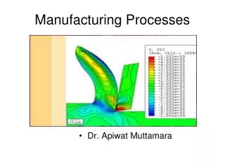
Metal Flow • Is quite complex. • Will impact quality and mechanical properties of product: must not overlook to prevent defects. • Extruded products have elongated grain structure. • Metal at center passes through die w/little distortion • Metal near surface undergoes considerable shearing. • Friction between moving billet and stationary chamber walls impedes surface flow. • Result is deformation pattern seen (fig. 15.7).
Extrusion can be Hot or Cold • Hot Extrusion (Fig. 15.3a) • Takes place at elevated temperatures. • Used in metals that have low ductility at room temperature. • Need to pre-heat dies to prolong die life and reduce billet cooling. • Hot working tends to develop an oxide film on the outside of the work unless done in an inert environment. • Solution: • place smaller-diameter dummy block ahead of ram before the billet. A layer of oxidized material is then left in the chamber, and is later removed and final part is free of oxides.
Extrusion can be Hot or Cold • Cold Extrusion (also know as Impact Extrusion) • Designated as cold when combined with other forging operations. (Fig. 15.11) • Slugs having less than 1.5” diam. are sheared / ends ground; larger slugs are machined. • Punch descends on a blank, which is extruded backward. • Slug dimensions and material, as well as lubrication are key variables. • Diameters up to 6” and thin walls can be made. • Collapsible tubes can be made this way (toothpaste tubes).
Advantages Cold vs. Hot Extrusion • Cold: • Better mechanical properties due to work-hardening. • Good dimensional tolerances & surface finish. • No need to heat billet. • Competitive production rates & costs. • Hot: • Larger variety of materials. • Less forces required. • Better material flow.
Hollow Shape Designs • Can make extrusion designs having multiple longitudinal cavities. (Fig. 15.2) • Spider, porthole or bridge dies are used. • Hot metal divides and flows around the internal spider shaped mandrel into strands. • Further reduction forces seams to close and re-weld given the high pressure and temperature in the chamber. • Since no metal has been exposed to contamination, perfect weld results. • Process is only good for aluminum / its alloys.
Die Designs • Non-ferrous metals use ‘square’ dies (α = 90 deg) • Non-ferrous metals are more softer/ductile than ferrous metals. • A dead metal zone will not be as catastrophic as for ferrous metals. • Using small die angles with ferrous metals causes increased pressure on the tooling. • Tubing can be made by having solid or hollow billets with or without the use of a mandrel. (fig. 15.19)
Guidelines for Die Design • Avoid sharp corners • Have similarly sized voids if possible. • Have even thickness in walls if possible. • General idea is to favor even flow. • See fig. 15.7
Lubrication • Essential in drawing to improve die life, reduce drawing forces/temperature, improve surface finish, particularly in hot extrusion. • Difficult to maintain a constant lubricant film constant between the die and the workpiece. • Can coat with zirconia to add life to die.
Benefits & Limitations • Benefits include: • Ability to extrude brittle materials. • Low friction. • Can use small die angles / high R values. • Can extrude metals / polymers. • Limitations • Limited industrial applications. • Complex tooling required. • Need specialized equipment.
Defects in Extrusions • Surface Cracking / Tearing • Occurs with high friction or speed. • Can also occur with sticking of billet material on die land. • Material sticks, pressure increases, product stops and starts to move again. • This produces circumferential cracks on surface, similar to a bamboo stem. (referred to as bambooing).
Defects in Extrusions • Pipe • When dead zones are produced, oxides /impurities are drawn to the center of the billet, like a funnel. • Requires scrapping the product. • Can minimize by modifying flow pattern to make it more uniform, modifying friction and temperature gradients. • Can also machine billet surface or chemical etch prior to extrusion.
Defects in Extrusions • Internal Cracking • Center of extrusion tends to develop cracks of various shapes. • Center, center-burst, arrowhead, chevron cracking. • Due to hydrostatic stress at CL in the deformation zone in the die. • Center cracking: • Increases with increasing die angle. • Increases with impurities. • Decreases with increasing R and friction.
Drawing • Definition (See Fig. 15.18) • Cross section of a round rod / wire is reduced by pulling it through a die. • Variables: • Die Angle a • Extrusion Ratio R (A0 / Af) • Friction between die and workpiece, drawing speed. • “There is an optimum angle at which the drawing force is minimum” for a given diameter reduction and friction parameter.
Drawing • Estimation of Drawing Force required: F = Yavg Af ln (A0/Af) • Yavg = average true stress of material in the die gap. • Assumptions: no friction.
Drawing • Work has to be done to overcome friction. • Force increases with increasing friction. • Friction increases, drawing force increases. • Cannot increase force too much, or material will reach yield stress. • Maximum reduction in cross-sectional area per pass = 63%.
Drawing Die Design • Die angles range from 6 to 15 degrees. • Two angles are typically present in a die: • Entering angle • Approach angle • Bearing Surface (land): sets final diameter. • Back relief angle
Defects in Drawing • Center cracking. • Seams (folds in the material) • Residual stresses in cold-drawn products. • If % reduction is small: • (Compressive at surface / Tensile at Center) • If % reduction is larger, opposite occurs: • (not desirable- can cause stress corrosion cracking.)