Download
1 / 3
30 likes | 132 Views
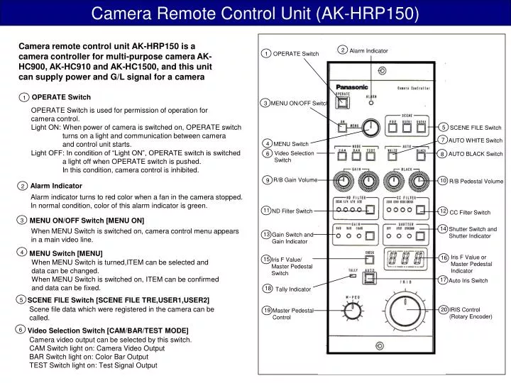
Camera Remote Control Unit (AK-HRP150). 6. 4. 3. 2. 1. 6. 5. 5. 8. 7. 1. 2. 3. 4. 9. 10. 15. 18. 20. 11. 19. 13. 14. 16. 17. 12.

E N D
Camera Remote Control Unit (AK-HRP150) 6 4 3 2 1 6 5 5 8 7 1 2 3 4 9 10 15 18 20 11 19 13 14 16 17 12 Camera remote control unit AK-HRP150 is a camera controller for multi-purpose camera AK-HC900, AK-HC910 and AK-HC1500, and this unit can supply power and G/L signal for a camera Alarm Indicator OPERATE Switch OPERATE Switch MENU ON/OFF Switch OPERATE Switch is used for permission of operation for camera control. Light ON: When power of camera is switched on, OPERATE switch turns on a light and communication between camera and control unit starts. Light OFF: In condition of “Light ON”, OPERATE switch is switched a light off when OPERATE switch is pushed. In this condition, camera control is inhibited. SCENE FILE Switch AUTO WHITE Switch MENU Switch Video Selection Switch AUTO BLACK Switch R/B Gain Volume R/B Pedestal Volume Alarm Indicator Alarm indicator turns to red color when a fan in the camera stopped. In normal condition, color of this alarm indicator is green. ND Filter Switch CC Filter Switch MENU ON/OFF Switch [MENU ON] Shutter Switch and Shutter Indicator When MENU Switch is switched on, camera control menu appears in a main video line. Gain Switch and Gain Indicator MENU Switch [MENU] Iris F Value or Master Pedestal Indicator Iris F Value/ Master Pedestal Switch When MENU Switch is turned,ITEM can be selected and data can be changed. When MENU Switch is switched on, ITEM can be confirmed and data can be fixed. Auto Iris Switch Tally Indicator SCENE FILE Switch [SCENE FILE TRE,USER1,USER2] Scene file data which were registered in the camera can be called. IRIS Control (Rotary Encoder) Master Pedestal Control Video Selection Switch [CAM/BAR/TEST MODE] Camera video output can be selected by this switch. CAM Switch light on: Camera Video Output BAR Switch light on: Color Bar Output TEST Switch light on: Test Signal Output
Camera Remote Control Unit (AK-HRP150) 7 8 9 13 17 20 18 16 19 15 14 11 11 10 Gain Switch and Gain Indicator [GAIN] AUTO WHITE Switch [AUTO WHITE] Video gain indicates as follows. AUTO WHITE Switch is used for automatic white balance. Light ON: This indicates to receive the start of automatic white balance by pushing AUTO WHITE Switch. Light ON and OFF:This alarms that white balance adjustment has not completed after automatic white balance adjustment. Light OFF: This shows that white balance adjustment has completed. 0dB 9dB 18dB 0dB 9dB 18dB Super Gain 1 Super Gain 2 Super Gain 3 AUTO BLACK Switch [AUTO BLACK] AUTO BLACK Switch is used for automatic black balance. Light ON: This indicates to receive the start of automatic black balance by pushing AUTO BLACK Switch. Light ON and OFF:This alarms that black balance adjustment has not completed after automatic black balance adjustment. Light OFF: This shows that black balance adjustment has completed. Shutter Switch and Shutter Indicator [SHUTTER ON] Electronic shutter speed which is selected by camera menu can be switched on and off. A light turns on when shutter function is selected. Iris F Value/Master Pedestal Switch [CHECK] Indication of Iris F value or M-PED value is switched every pushing this switch. R/B Gain Volume [R/B GAIN] Iris F Value or Master Pedestal Indicator Red and blue level can be adjusted by these gain volumes. Automatic white balance adjustment can be controlled. Iris F value or master pedestal value is displayed in this indicator. Auto Iris Switch [AUTO] R/B Pedestal Volume [R/B PED] Auto iris operation works by pushing this switch. Light ON: Auto Iris Condition Red and blue pedestal can be adjusted by these pedestal volumes. Automatic black balance adjustment can be controlled. Tally Indicator ND Filter Switch [ND FILTER] Tally light turns on when there is a tally input in external tally connector. This switch can be used for ND filter selection. ND-1: 100% ND-2: 25% ND-3: 6.3% ND-4: 3.2% Master Pedestal Control Master pedestal can be controlled by this controller. Master pedestal increases by rotating this controller clockwise. Master pedestal and R/G/B pedestal are independent, then R/G/B pedestals do not change when master pedestal is changed. CC Filter Switch [CC FILTER] This switch can be used for CC filter selection. CC-A: 3200K CC-B: 4300K CC-C: 6300K CC-D: Cross IRIS Control (Rotary Encoder) Lens iris level can be controlled by this controller.
Camera Remote Control Unit (AK-HRP150) 1 2 3 9 7 6 5 8 4 3 2 3 2 1 1 CONNECTORS CONNECTORS Camera I/F Connector (HIROSE:HDAB-15S) Description Description Y OUT 9 Pb GND 1 Pb OUT 10 Pr GND 2 11 • Direction of DATA • TXD:CAM Controller • RXD:Controller CAM 3 Pr OUT Tally Connector G/L GND 12 4 G/L IN DC12V GND 13 5 DC12V IN TX GND 6 GND 14 RXD 7 TXD 15 RXD GND Power Connector 8 Y GND 16 Camera I/F Connector Tally Connector (HIROSE:HR10A-7R-4P) Power Connector Description Description DIMENSIONS GND R TALLY 1 1 N.C. 2 2 N.C. 65 N.C. N.C. 3 3 R TALLY COM 4 DC12V 4 15 6.5 SPECIFICATIONS 15 Control Item:Refer to control panel description. Operating Temperature: 0°C~+40°C (32°F~104°F) Storage Temperature:-20°C~+60°C (-4°F~140°F) Weight:Approx.1.2kg (2.65lbs) 228.2 225 242 225 Dimensions:92(W)X225(H)X65(D)mm (3-5/8WX8-7/8HX2-9/16D) Camera Interface Connector:D-SUB 15pin Female Synchronous Signal:REF Input(GL Input:Tri Level SYNC) Control System:Asynchronous System(TX/RX signal:RS422) 60 Tally Input:Contact Closure input 32 Input Power:DC12V (Cannon 4pin connector) 10 6.5 CONTROL CABLE A control cable (5m) is included in this unit as a standard accessory.