Download
1 / 31
310 likes | 469 Views
Task Overview. Create a dynamic model of the spacecraft Account for the environmental disturbances Evaluate the dynamic response of the spacecraft Observe roll, pitch, yaw in time and frequency domains Interface with the other teams to meet mission requirements. Status at PDR.

E N D
Task Overview • Create a dynamic model of the spacecraft • Account for the environmental disturbances • Evaluate the dynamic response of the spacecraft • Observe roll, pitch, yaw in time and frequency domains • Interface with the other teams to meet mission requirements
Status at PDR • Initial point mass dynamics completed • J2, atmospheric drag, and solar pressure quantified • Orbital elements calculated • Two-mass model of body created • Determined stiffness, damping m2 m1
RFAs From PDR • Provide a detailed analysis of loads from two mass model (Prof. Pellegrino) • Directive: switched to rigid body model, now a structural task • Account for J3 and solar activity if long term orbital elements are important (Dr. Watkins) • Accepted for advisory: Insufficient time to analyze complete effect • Deliver accelerations to predict loads to structures, and attitude history for thermal (Prof. Quadrelli) • Action item: accelerations given to structures, attitude history not incorporated into thermal model
Receivables • Project: • 300 microradian control • 120 microradian knowledge • Orbit description • Structures: • Moments of inertia for response • Modal frequencies for controller design • Metrology: • Asserted that the mission requirements were sufficient
Baseline Approach for Modeling Disturbances • Disturbances Modeled • Solar pressure, Atmospheric drag, and Earth’s Oblateness. • Formulation • AGI-Satellite Kit-3rd party software used to predict Keplerian Orbital parameters. • Matlab used for • Independent verification of AGI-Satellite Kit results. • Integrate the disturbance models with the rigid body dynamics.
Reference Frame • Earth Centered Inertial Frame (XYZ) • S/C starts at Perigee • Convert the initial condition from orbit to ECI frame • [Ixyz]=[R][Iorbit]
Input Parameters • Physical Data • Satellite Mass ~ 330kg • Drag Cross-Sectional Area ~ 10m2 • Solar Radiation Pressure Cross-Sectional Area ~ 10m2 • Area-to-Mass Ratio β ~ 0.019 m2/kg • Ballistic Coefficient (B = M/Cd*A) ~ 15 (kg/m2) • Drag Coefficient Cd ~ 2.2
AGI-Satellite Kit • Assumptions • Orbit Start : 1st July 2012 • Orbit Stop : 2nd July 2014 • Time Step between calculated Ephemeris - 50sec • J2 Coordinate System with Keplerian Orbit Elements • Long-Term-Orbit-Predictor (LOP) • Force Models • Atmospheric Drag • Exponential Density Model • Osculating Altitude • Earth’s Oblateness i.e J2 effect • Solar Radiation Pressure • Perfectly Black Body assumption (Solar Radiation Constant Cp = 1)
MATLAB • Algorithm • ODE45 Solver (Runge-Kutta method) • Forces • Solar Pressure • Neglected seasonal variations • Nominal Solar Pressure Radiation constant fp = 4.5*10-6 (N/m2) • Reflectivity ref = 0 ( worst case i.e Black Body) • Atmospheric Drag • Exponential Model for the Density • Earth’s Oblateness – J2 effect
Orbital Lifetime Results (STK) 27 Deg Inclined Orbit 5 Deg Inclined Orbit 13
Attitude Model • Goal: Predictive capability of attitude dynamics, and provide framework for developing ACS • Assumptions • Circular orbit • J2 and gravity forces are only system torques • Model is linearized about the stable pointing (Jyy towards Earth) • White noise on angle rates (10-7 rad/s) • PD controllers • Gains tuned manually • Goal is 250s settle time from 1 degree offset for pitch, or 1 degree yaw/0.1 degree roll for roll-yaw • Reaction wheels saturate at 0.01 Nm torque and 20 Nms angular momentum • Two wheels in roll direction 14
Coordinate System • Yaw about x-axis, Pitch about y-axis (out of plane), Roll about z-axis
Attitude Model Equations are for RPY angles and rates. Source: Tewari, Section 14.7.2 16
Verification • Theoretical pitch frequency calculated from Wertz, p.610: • Model libration frequency is very close to the theoretical • Model: 0.0018 rad/s ~ 0.28 mHz • Theoretical: 0.0019 rad/s ~ 0.30 mHz 17
Integrated Model • 6 DOF model of attitude and orbit data • Orbit should be independent of attitude to first order • Attitude does not affect orbit, but orbit data is input to attitude dynamics • Integrated model uses same assumptions as independent attitude and orbit models • Check librations and controllers with simulated orbit data • Compare to stand-alone attitude model • White noise on rates is disturbance • 10-7 rad/s standard deviation 19
Integrated Model Results Yaw is not stable because Jxx = Jyy. 20
Settling Times • Settling times calculated for both independent attitude dynamics model and integrated model • Noise included in model • Settling times calculated separately for pitch; roll and yaw calculated together • Initial conditions • For pitch model: • 0 degree roll, 1 degree pitch, 0 degree yaw • No angle rates • For roll-yaw model: • 0.1 degree roll, 0 degree pitch, 1 degree yaw • No angle rates 22
Controller tuning Manually tuned PD controllers to achieve fastest settling times accounting for saturation Settling Times 23
Deliverables • Project: • Coded model • PD controller • Structures: • Accelerations from torques • Controller frequencies • Metrology: • Performance of controller (long-term) • Relation of controllability and observability (long-term)
Incorporating cross-sectional area Changes over time Incorporate 3D model Evaluating reaction wheels trade Torque vs. extra mass Performance of known options Optimizing controller 100s settling time from 1 degree Open Issues and Concerns 25
Summary • Created dynamics model • Predicts orbital elements with disturbances • Verified with STK • Created attitude model • Predicts controller performance in linear region • Verified with pitch frequency • Integrated the two models • Driven by white noise • 256 second pitch settling time
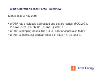
Review Protocol Requests for Action (RFAs) will be categorized as follows: • Action Items (AIs) • Formal write-up required to close • Results presented at CDR • Directives • Recommendations for design improvements or investigations • Informal write-up required to close • Summary of all directive results presented at CDR • Advisories • Recommendations for investigations or identification of problems • No formal closures
Functional Requirements Summarize your subsystem functional requirements derived from Level 1s : • 300 microradians axis pointing accuracy • .0075 radion rotation about z-axis • Response time? • Torque required? 30
Level 1 Requirements Summarize Level 1s from Project relevant to your subsystem: • Pointing accuracy • Stability • Orbital requirements