Download
1 / 11
110 likes | 291 Views
Circuits of Second Order. Abreu Fernández Emilio David Badillo Sotelo Hugo Adrián Carrión San Juan Juan Manuel Carrizoza Rivas José René Moreno Muzqueño José Marcos. Introduction:.

E N D
Circuits of Second Order Abreu Fernández Emilio David Badillo Sotelo Hugo Adrián Carrión San Juan Juan Manuel Carrizoza Rivas José René Moreno Muzqueño José Marcos
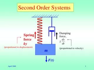
Introduction: • In this subject the circuit analysis of second order is introduced, that is the circuits governed by equations of second order. The complexity of its operation is pronounced in the calculation of the natural answer where they appear three possible ways of operation. • Resistive circuits, Capacitive and Inductive. • They are all those circuits that contain a resistance, a capacitor and a coil.
Capacitor, place of energy storage, that allows a stable constant flow of the same, stores energy, can unload a short one. Coil, conductive wire in the form of spirals, of n I number of returns, that are against the change of sense of the current, also stores something of energy against-FEM, besides generating magnetic fields inducing voltage or electric fields inducing magnetism. • Circuit RL - Inductive Resistive • Circuit RC- Capacitive Resistive • Circuit RLC-Capacitive Inductive Circuit
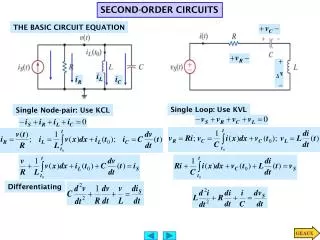
We define electric current in a specific volume and the change in charge from the inside of the volume in unit time and its unit is the ampere. I (t) = dq/dt • We define voltage as the energy per unit charge created in the separation of freight and its unit is the Volt. V (t) = dW/dq • We define electric power as the energy change per unit time and its unit is the Watt. P (t)=I (t) V (t)
The RLC Circuit Analysis AC is a branch of electronics that details the resolution of the equations defining these circuits, allowing the analysis of its operation. Apart from knowledge of electronics, are necessary elements of mathematical analysis and the use of differential equations and complex numbers as well as Fourier and Laplace transforms. In these circuits, electromagnetic waves usually appear as phasors characterized by its magnitude and phase, allowing for easier analysis.
An RLC circuit is a circuit where there are only resistors, capacitors and inductors, these three elements have characteristics of linear equations (linear system) between voltage and current. It says there are no active elements. • Resistance: V (t) = I (t) * R; • Condenser; I (t) = C du(t)/ dt • Coil; u (t) = L di(t) / dt
Applying Kirchhoff’s laws to solve a system of differential equations to determine the voltage and current in each of the branches. Since this process is extremely laborious from a circuit that is more than two coils or condensers (would be faced with more differential equations of second order), what is done in practice is to write the circuit equations and then simplify through the Laplace transform, in which derivatives and integrals are addition and subtraction with complex numbers, is often called the complex domain, solving a system.
The Laplace transform of the RLC circuit elements, is the equivalent circuits used to solve is: • Resistance: Z = R + j * 0 That is, no imaginary part. • Condenser: So no real part. W is the frequency of the circuit with f the frequency of the current flowing through the circuit and the capacitor C • Coil: So no real part. W is the frequency of the circuit () with f the frequency of the current flowing through the circuit and L is the inductance of the coil.
Generalization of Ohm's law: • The tension between the ends of impedance is the product of current through the impedance: Both the impedance and the current and voltage are generally complex. Impedances in series or parallel Vz = Z I z
The result of a calculation of a voltage or a current is usually a complex number. This complex number is interpreted as follows: • The module indicates the value of the voltage or current calculated. If the values used for the generators were peak values, the result will also be a peak value. If the values were effective values, the result will also be an effective value. • The argument of the complex number gives the gap with the generator used as phase reference. If the argument is positive the voltage or current will be calculated in advance stage.
Circuits with different frequency sources • We are the problem that arises when calculating the impedances of capacitors or inductors in our circuit, each with different sources often have a different keystroke, so for the same circuit, a capacitor could have as many different sources impedances with different frequency.