Download
1 / 30
300 likes | 350 Views
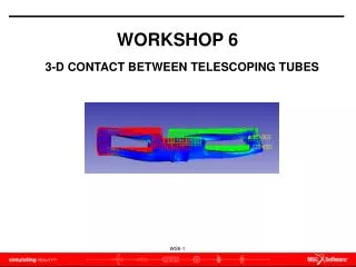
WORKSHOP 6 PERFORMING A DESIGN STUDY. WORKSHOP 6 - PERFORMING A DESIGN STUDY. Problem statement

E N D
WORKSHOP 6 PERFORMING A DESIGN STUDY
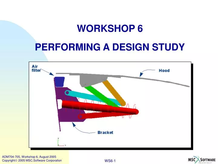
WORKSHOP 6 - PERFORMING A DESIGN STUDY • Problem statement • In this workshop, you will study the effect of changing the length of the links in the hood mechanism. You will learn how to create design variables, use them in your parametric model, and perform a design study to see the effect that these variables have on the hood motion.
WORKSHOP 6 - PERFORMING A DESIGN STUDY • In Workshop 5 – Parameterizing a New Model, you created a parametric model of the hood mechanism by using design points. You learned that the model configuration could be altered by moving the points to new locations. You also identified some shortcomings with that approach. In this workshop, you will define the parametric relationships in a different way so that you eliminate the shortcomings and perform a design study.
WORKSHOP 6 - PERFORMING A DESIGN STUDY • Getting started To import the model: • Start ADAMS/View from the mod_06_hood_DS directory. • Import the parameterized hood model, hood_2_start.cmd. • From the Settings menu, select Names. • In the Default Names dialog box, select Full names. • Select OK.
WORKSHOP 6 - PERFORMING A DESIGN STUDY • Creating design variables • In general, you need to identify the parameters in a model that you want to represent with design variables. In deciding which model parameters would make good design variables, you'll find there are a variety of choices you could make. In this example, you'll consider a physical characteristic, such as length, and an assembly characteristic, such as assembly angle.
WORKSHOP 6 - PERFORMING A DESIGN STUDY • You will define link lengths and assembly angles through design variables (L1, L2 and A1, A2, respectively). Then, you will prescribe the point locations of POINT_2, POINT_3, and POINT_4 so they are dictated by these design variables through the use of design-time expressions.
WORKSHOP 6 - PERFORMING A DESIGN STUDY • To create design variables: • From the Build menu, point to Design Variable, and then select New. Create design variables with parameters as shown in the table below. Tip: You may find it easier to use the command line to create the variables.
WORKSHOP 6 - PERFORMING A DESIGN STUDY • From the Tools menu, select Table Editor. • At the bottom of the Table Editor, choose Points, and then select Filters. The Points Table Editor Filters dialog box opens. Notice that all points are currently listed in the Table Editor. Next, reduce the set of points so only those of interest are shown. • From the Points Table Editor Filters dialog box, select Single Column for X,Y,Z and use a Name Filter of *POI*. • Select OK. The number of points listed has been reduced by the filtering operation.
WORKSHOP 6 - PERFORMING A DESIGN STUDY • Using cylindrical coordinates
WORKSHOP 6 - PERFORMING A DESIGN STUDY • To use cylindrical coordinates to redefine POINT_2 relative to PT_A with the design variables L1 and A1: • Select the location for POINT_2. • Right-click in the text box located at the top of the dialog box, point to Parameterize, and then select Expression Builder. • In the Function Builder, replace the existing location with the following: (LOC_RELATIVE_TO(LOC_CYLINDRICAL(L1,A1,0),.hood1.ground.PT_A)) • Select Evaluate to check the syntax. • Select OK. The function has been sent to the Table Editor. • In the Table Editor, select Apply. The point location is now defined by this expression.
WORKSHOP 6 - PERFORMING A DESIGN STUDY • Using the procedure described in Using cylindrical coordinates (or your own method), redefine POINT_4 relative to PT_B using the design variables L2 and A2. Use the following nested location expression: (LOC_RELATIVE_TO(LOC_CYLINDRICAL(L2, A2, 0),.hood1.ground.PT_B)) • Using the procedure described in Using cylindrical coordinates, redefine POINT_3 to be located between PT_B and POINT_4 (as shown in figure below). Use D1 as a multiplier for % offset from PT_B along the line. Use the following location expression: (LOC_ALONG_LINE(PT_B, POINT_4, D1*DM(PT_B,POINT_4) ))
WORKSHOP 6 - PERFORMING A DESIGN STUDY • Sweeping variables • Now that your design variables have been implemented in the points, you should make sure they work properly. The usual way to do this is to modify them and change the standard_value, testing the upper and lower limits and the values in between. To make this easier for you, we have provided a custom macro and menu button (sweep) that will sweep a design variable between its upper and lower limits.
WORKSHOP 6 - PERFORMING A DESIGN STUDY • To sweep variables: • Use the F2 key and import utils/DV_sweep/load_sweep_mac.cmd. This loads the macro into your database and creates a custom menu button. • Use the custom menu button: • From the Build menu, point to Design Variable, and then select Sweep. • In the Variable Sweep dialog box, sweep D1 to see how it works. • Sweep A1, noticing that POINT_1 isn't staying on the point of intersection between the links. You will fix that problem in the next section. • Sweep the remaining variables, L1, L2, and A2, to confirm that they're being used correctly.
WORKSHOP 6 - PERFORMING A DESIGN STUDY • Locating a point at an intersection of two lines • As you observed in Workshop 5 – Parameterizing a New Model, one of the shortcomings of parameterizing by points only was that interdependencies weren't captured. In the hood mechanism you saw that POINT_1 should lie at the intersection of the lines PT_A-to-POINT_2 and PT_D-to-POINT_3. You can calculate this intersection mathematically and store it in an ADAMS/View user-written function. This function can then be used to define the location of POINT_1.
WORKSHOP 6 - PERFORMING A DESIGN STUDY • To locate a point at an intersection: • Change the appearance of POINT_1 to be blue so that it's easier to see. • The algebraic mathematics needed to find the intersection of two lines from four points are rather involved. Using a text editor, review the contents of find_intersection.cmd (in the Misc folder) to see the syntax for creating the user-written interpreted function, INT_PT. • How many input arguments are used? 2 3 4 • How many output values are returned? 2 3 4
WORKSHOP 6 - PERFORMING A DESIGN STUDY • Would you like to type the lengthy expression text by hand every time you wanted to calculate an intersection? ____Yes ____No Note: For information on finding the intersection point of two lines and parameterizing its location, see the Knowledge Base Article 8901, available at: http://support.adams.com/kb/faq.asp?ID=kb8901.dasp • Import the INT_PT user-written interpreted function to calculate the intersection of two lines from four points in a plane. Tip: Use the F2 key to quickly import the file find_intersection.cmd (in the Misc folder).
WORKSHOP 6 - PERFORMING A DESIGN STUDY • Set POINT_1 to lie at intersection of the lines PT_A-to-POINT_2 and PT_D-to-POINT_3 by using the INT_PT user-written interpreted function. • In the Table Editor, select the location for POINT_1. • Right-click in the text box located at the top of the dialog box, point to Parameterize, and then select Expression Builder. • In the Expression Builder, set the function category to Location/Orientation. • From the selection menu, highlight your new function, INT_PT. • Double-click the function and modify the syntax in your workspace to look like the following: INT_PT(PT_A, POINT_2, PT_D, POINT_3) • Select OK to close the Expression Builder. • Select Apply in the Table Editor.
WORKSHOP 6 - PERFORMING A DESIGN STUDY • Test the behavior of the INT_PT function by modifying a design variable and observing whether or not POINT_1 updates parametrically. Use Sweep Variable and sweep D1. Notice that the Intersection function (INT_PT) works as desired and all interdependencies are correctly maintained.
WORKSHOP 6 - PERFORMING A DESIGN STUDY • Defining a measure to study • Soon you will run design studies for several of the design variables. A little later in the course, you will optimize the model using all the design variables. Both of these analysis types are known as multi-run simulations, and their command language requires a measure or an objective as one of the input parameters. • Remember that you want to design the linkage so the hood never touches the filter as it is opened. Therefore, a measure of that is what you want to study in the design study. As you recall from Workshop 5- Parameterizing a New Model, there was a pre-existing measure FUNCTION_MEA_Y that measured the distance from a marker on the rear of the hood to the top surface of the filter. When the value of that measure became negative, you knew that the hood was penetrating the filter and was, therefore, an unacceptable linkage design.
WORKSHOP 6 - PERFORMING A DESIGN STUDY • As you become more familiar with optimization objectives and constraints, you will learn that the sign of a measure (+ or -) has special meaning. For example, if an optimization constraint is positive, then it has been violated. If it is negative, it has not been violated and the design is considered acceptable. To begin thinking along those lines, modify the FUNCTION_MEA_Y so that a positive value of the measure indicates that the hood marker has interfered with the filter's top surface. Conversely, if the measure stays negative throughout the operation cycle, it means that it's an acceptable linkage design.
WORKSHOP 6 - PERFORMING A DESIGN STUDY • To define a measure to study: • Modify FUNCTION_MEA_Y. Tip: Build Measure Function Modify, then select FUNCTION_MEA_Y. Negate the DY function expression so it appears like this:-DY(.hood1.PART_1.MARKER_rear, .hood1.ground.top_surf, .hood1.ground.top_surf) • If the strip chart is not already displayed, display it. Note: Later in Workshop 8 - Optimization, you will use this measure as a design constraint in an optimization. Now that you’ve negated it, it’s ready to use. • Run a baseline simulation (1 sec/50 steps) from the Main Toolbox and review how the mechanism operates and what the measure looks like. • Does the measure stay negative throughout the simulation? _____ Yes _____ No
WORKSHOP 6 - PERFORMING A DESIGN STUDY • Performing a design study • Here you will study the effect of L1 on the hood opening behavior by performing a design study. To perform a design study: • From the Simulate menu, select Design Evaluation, and complete the Design Evaluation Tools dialog box as follows: • Simulation Script: Last_Sim • Study a: Maximum of • Measure: FUNCTION_MEA_Y • Select Design Study radio button • Design Variable: L1 • Default Levels: 5
WORKSHOP 6 - PERFORMING A DESIGN STUDY • Select Start to initiate the design study. • When the design study has finished, generate a tabular summary report of the design study by clicking the icon at the bottom of the dialog box. Use the default options and select Ok. • Briefly review its contents. • Study the effect of A1 by running a similar design study. • Which trial(s) in this design study had some strange or unexpected linkage behavior? • What was the value of A1 for that trial? ______________________________________ • Reduce the lower bound for variable A1 so the absolute range is: -15, +10.
WORKSHOP 6 - PERFORMING A DESIGN STUDY • To run the design study again: Now you'll run the design study of A1 again, using the new range. First you will make some settings that will allow the multi-run simulations to run faster, while still giving you visual feedback of the opened hood for each design configuration. • In the Design Evaluation Tools dialog box, select the Display button. The Solver Settings dialog box opens. • Complete the dialog box as follows: • Category: Display • Update Graphics: At Simulation End • Toggle the More button at the bottom left of this dialog box. • Update Toolbar: At Output Step • Chart Objective: Yes • Save Curves: Yes • Show Report : Yes • Select Close.
WORKSHOP 6 - PERFORMING A DESIGN STUDY • Run another design study of A1. • Did the study exercise A1 through its new range (-15 to 10)? _____ Yes _____ No • Does the range on the variable seem well-bounded now? Why or why not? ________________________________________________________________________________________________________________ • In which trial(s) did the objective stay negative (that is, the hood didn’t touch the filter)? ___________________ • Close the Information window. • Export the model in command file format as after_DS.cmd.
WORKSHOP 6 - PERFORMING A DESIGN STUDY • Setting the design variable to values used in a trial • Here you will run the simulation using the value obtained from the previous design study. To set the design variable: • Using the Set Variables tool set the design variable A1 to the value from the trial where the objective was the maximum negative value (either trial 1 or trial 2). • Run an individual simulation and animate the results. • Save the database. • If time permits, complete some of the optional tasks.
WORKSHOP 6 - PERFORMING A DESIGN STUDY • Optional tasks • Run more design studies. • Set the output settings to Save Analyses for both individual simulations and multi-run simulations. Perform a design study and select the Plot Results tool from the dialog box to generate the plots. Review the various plots that are created. • If you run an additional design study, will it overwrite the saved analyses or create a series of new ones with similar naming structure? ___________________________________________________________ • Do you know how to delete the analyses from the database? Please explain. ___________________________________________________________
WORKSHOP 6 - PERFORMING A DESIGN STUDY • Experiment with sliders. • Import the file utils/DV_live_slider/hood_variable_control.cmd. This displays a customized dialog box with sliders to control the values of the design variables. Experiment with different settings and run simulations. • Run design studies of design variables D1, L2, A2. • Run design study using list of values. • Modify one of the design variables so that it is defined by a list of values. Run a design study of that variable and review the summary report to see if it actually used the list of values you provided. • Was the list of values used? ____Yes ___No • Select Allow Design Study to ignore list on the design variable modify dialog box. Run a design study again. • Did it ignore your list of values? ____Yes ___No
WORKSHOP 6 - PERFORMING A DESIGN STUDY • Answer the following questions: • Do you think it's possible to study more than one measure at a time? ____Yes ___No Try it. • How about studying more than one objective at a time. Do you think that would work? _____ Yes _____ No Try it. Tip: Make two objectives, average value and minimum absolute value. • Run design studies of the remaining variables (D1, L2, A2). See how the mechanism behaves as the design variables sweep throughout their ranges. • Do the design variable ranges seem well bounded? ___Yes ___No