Download
1 / 8
80 likes | 173 Views
Lower Latency R3-Data: Summary. Muons suggest 15us latency is possible with current hardware R3 into ABC → R3-data out HCC in 5 µ s? Areas where “improvements” can be made to reduce latency: Increase bandwidth Simply double all link rates in the system Separate links for R3 and L1

E N D
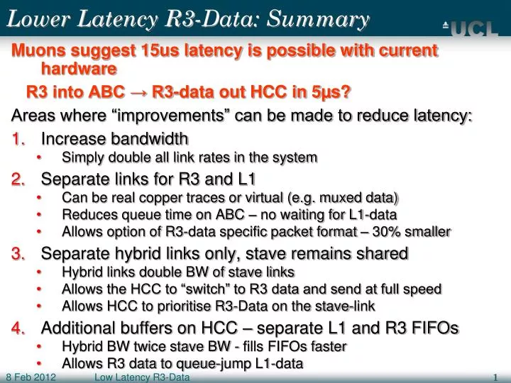
Low Latency R3-Data Lower Latency R3-Data: Summary Muons suggest 15us latency is possible with current hardware R3 into ABC → R3-data out HCC in 5µs? Areas where “improvements” can be made to reduce latency: • Increase bandwidth • Simply double all link rates in the system • Separate links for R3 and L1 • Can be real copper traces or virtual (e.g. muxed data) • Reduces queue time on ABC – no waiting for L1-data • Allows option of R3-data specific packet format – 30% smaller • Separate hybrid links only, stave remains shared • Hybrid links double BW of stave links • Allows the HCC to “switch” to R3 data and send at full speed • Allows HCC to prioritise R3-Data on the stave-link • Additional buffers on HCC – separate L1 and R3 FIFOs • Hybrid BW twice stave BW - fills FIFOs faster • Allows R3 data to queue-jump L1-data
Low Latency R3-Data Latency Context Plan is to roughly split 15µs between L0, R3 and L1: • BC to issuing L0 (at ABCs) – 4µs • Includes cable time (also used by R3) • RoI-ID → R3 0.5µs • Transfer to TTC • TTC distribution • ROD processing, incl. serialising for stave • R3 at ABC to R3-Data leaving HCC 5µs • Transfer to ROD/Trackfinder (100m) 0.5µs • Trackfinding 4µs • Merge with other L1 decisions 0.5µs • Send to Front-Ends (synchronous, 500m) 0.5µs
Low Latency R3-Data More on Separate Links • Can be extra copper, or multiplexed on same line • Of no consequence to simulations • Needs extra/muxed Xon/Off lines too • Links are divided 50/50 between L1 and R3 data • R3 data volume is ~10% of L1 data volume • Not the best link utilisation, but better for peak rates • Links can be completely separate (ABC to ROD) • Allows for differing packet formats on each link • R3-data packets 30% smaller • Stave link can be shared with hybrid link separated • Keep common packet format • XOn/Off can be applied independently to each hybrid link allowing the HCC to prioritise R3-Data per packet
Low Latency R3-Data 40 Mb 80 Mb 160 Mb 10 Chip Chain 160 Mb all the way, combined L1, R3 data (“shared 160, shared 160”) ABC HCC GBT Separated R3 and L1 data (“80+80, shared 160”) 80+80 on hybrid and stave ABC HCC GBT
Low Latency R3-Data 40 Mb 80 Mb 160 Mb 5+5 Chip – Combined Readout Link Combined L1, R3 data • 80 Mb per 5 chips (“shared 80, shared 160”) • Option to double above (“shared 160, shared 320”) HCC GBT ABC 4x40 2x80
Low Latency R3-Data 40 Mb 80 Mb 160 Mb 5+5 Chip - Separate Readout Links L1 and R3 data use independent links so no queuing - 40+40 x2 hybrid, 80+80 stave (“40+40, 80+80”) - Option to double the above (“80+80, 160+160”) HCC GBT ABC 4x40 2x80
Low Latency R3-Data 40 Mb 80 Mb 160 Mb 5+5 Chip - Separate on Hybrid Only Independent links on hybrid only (“80+80, shared 160”) Hybrid BW is TWICE stave BW HCC “switches” between R3 and L1 data HCC GBT ABC 4x80 160
Low Latency R3-Data 40 Mb 80 Mb 160 Mb 5+5 Chip - HCC with FIFO R3 and L1 data fill separate FIFOs on HCC Fill rate is double drain rate - allows R3 Data to “queue jump” FIFO’s need only be ~5-10 levels deep to match chips Note, for simulation purposes, this is nearly identical to the previous configuration (“shared 160, shared 160”) HCC L1-FIFO GBT ABC R3-FIFO 2x160 160