Download
1 / 15
150 likes | 399 Views
Example. SBUF Register. SCON Register(1). SCON Register(2). SCON Register(3). Serial Data Transmission Modes: Mode 0. In this mode, the serial port works like a shift register and the data transmission works synchronously with a clock frequency of fosc /12.

E N D
Serial Data Transmission Modes: Mode 0 • In this mode, the serial port works like a shift register and the data transmission works synchronously with a clock frequency of fosc /12. • Serial data is received and transmitted through RXD. • 8 bits are transmitted/ received at any time. • Pin TXD outputs the shift clock pulses of frequency fosc /12, which is connected to the external circuitry for synchronization.
Serial Data Transmission Modes: Mode 1 • In mode-1, the serial port functions as a standard Universal Asynchronous Receiver Transmitter (UART) mode. • 10 bits are transmitted through TXD or received through RXD. • The 10 bits consist of one start bit (which is usually '0'), 8 data bits (LSB is sent first/received first), and a stop bit (which is usually '1'). • Once received, the stop bit goes into RB8 in the special function register SCON. The baud rate is variable.
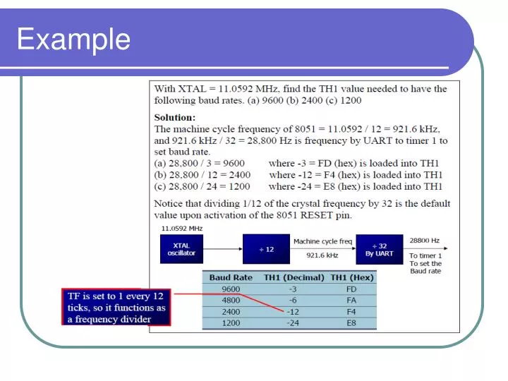
Mode 1 Baud Rate generation(1) • Timer-1 is used to generate baud rate for mode-1 serial communication by using overflow flag of the timer to determine the baud frequency. • Timer-1 is used in timer mode-2 as an auto-reload 8-bit timer. • The data rate is generated by timer-1 using the following formula. • It can be noted that fosc/ (12 X [256- (TH1)]) is the timer overflow frequency in mode 2
Mode 1 Baud Rate generation(2) • If timer-1 is not run in mode-2, then the baud rate is,
Serial Data Transmission Modes: Mode 2 – Multiprocessor Mode • In this mode 11 bits are transmitted through TXD or received through RXD. • The various bits are as follows: a start bit (usually '0'), 8 data bits (LSB first), a programmable 9 th (TB8 or RB8)bit and a stop bit (usually '1'). • While transmitting, the 9 th data bit (TB8 in SCON) can be assigned the value '0' or '1' . • For example, if the information of parity is to be transmitted, the parity bit (P) in PSW could be moved into TB8. • On reception of the data, the 9 th bit goes into RB8 in 'SCON', while the stop bit is ignored. • The baud rate is programmable to either 1/32 or 1/64 of the oscillator frequency.
Serial Data Transmission Modes: Mode 3 – Multiprocessor Mode with variable baud rate • Mode-3 is same as mode-2, except the fact that the baud rate in mode-3 is variable (i.e., just as in mode-1).
Steps for writing the code to transmit the character bytes serially
The steps that 8051 goes through intransmitting a character via TxD