Download
1 / 16
160 likes | 171 Views
Lab measurements and simulations of hips previously presented APV measurements* assumed signal divided equally between 7 channels -> significant deadtime predictions for CMS but relative absence of –ve saturated baseline events (no signal) in test beam data

E N D
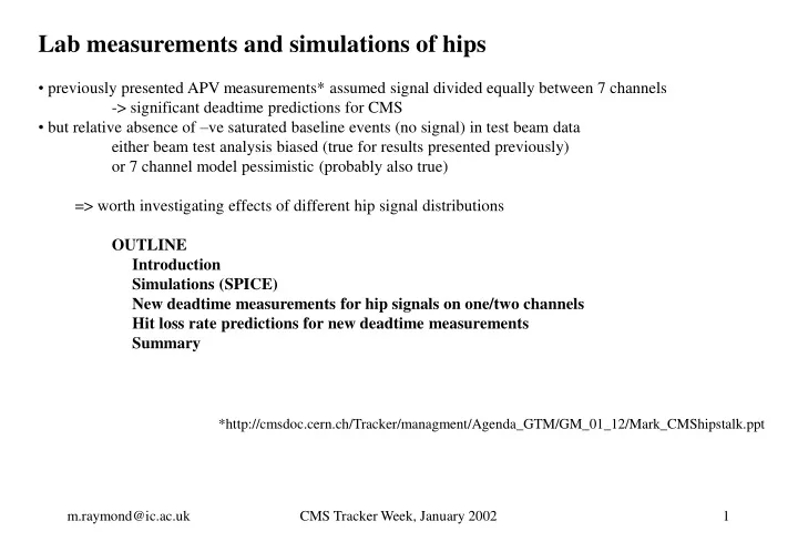
Lab measurements and simulations of hips • previously presented APV measurements* assumed signal divided equally between 7 channels • -> significant deadtime predictions for CMS • but relative absence of –ve saturated baseline events (no signal) in test beam data • either beam test analysis biased (true for results presented previously) • or 7 channel model pessimistic (probably also true) • => worth investigating effects of different hip signal distributions • OUTLINE • Introduction • Simulations (SPICE) • New deadtime measurements for hip signals on one/two channels • Hit loss rate predictions for new deadtime measurements • Summary *http://cmsdoc.cern.ch/Tracker/managment/Agenda_GTM/GM_01_12/Mark_CMShipstalk.ppt CMS Tracker Week, January 2002
saturated signals in 4 strips in this example Introduction X5 hip event ~ 8 mip range • X5 hip event shows up as saturated signals in • several channels • APV output range only ~ 8 mip (0.7 MeV) so no • information on actual signal size in saturated channels • First measurements on APV modelled hip charge shared equally between 7 channels • (choice simply governed by number of chans available on test setup) • Recoil nucleus should have short range (e.g. < 43mm for E < 100 MeV) but true situation more complicated • V. large signals on one/two channels still give > 0.7 MeV signals on neighbours due to inter-channel • capacitance CMS Tracker Week, January 2002
SPICE simulations • motivation: can’t see what’s going on inside chip otherwise • model: 128 channels with nearest neighbour interstrip • capacitance (10pF) and AC coupling to APV I/P • preamp o/p (after s.f.) linear to ~ 50 mips (4.5 MeV) • inverter O/P linear to ~35 mips (3.2 MeV) • signals > ~ 50 mips on a single channel cause that • channels inverter to draw max current • -> significant voltage disturbance on vCM R (on hybrid 1/chip) vCM APV sensor preamp inverter s.f. vi hip signal vo = -vi + vCM source follower O/P inverter O/P 10 10 mip steps 80 mip CMS Tracker Week, January 2002
Simulations (2) R (on hybrid 1/chip) source follower O/P vCM vCM nearest neighbours preamp inverter s.f. vo = -vi + vCM vi hip channel inverter O/P • results here for 200 mip (18 MeV) signal on one channel only • saturated signal in hip channel • big signal in nearest neighbours (~25 mip), shorter duration • combination -> transient disturbance vCM on R • vCM disturbance couples to inverter O/Ps of all channels • reduced value of R reduces effect • “spikey” behaviour of vCM interesting, could be decoupled non-hip channel CMS Tracker Week, January 2002
Lab measurements - “improved” setup for charge injection 10pF previous this study 10pF hip charge injected on one or two channels other channels see signal due to interstrip capacitance 7 APV I/Ps see hip charge shared equally 10pF 10pF 10pF 10pF 111 mips 500 mips 1111 mips • These results for hip charge injection on one channel only • Inter-channel capacitance -> signal sharing and saturated • signals in several channels • i.e. localised hip signal still shows results consistent • with beam data 45 MeV 100 MeV 10 MeV CMS Tracker Week, January 2002
Deadtime measurement technique Inject and measure amplitude (in APV O/P frame) of normal size signal sweep injection time of hip signal normal signal disappears during period when hip signal causing baseline saturation for all channels unplug normal signal and repeat to get baseline subtract baseline measurement from measurement with signal -> result gives deadtime = period during which the chip is insensitive to signals all measurements here in deconvolution mode trigger on normal signal inject normal signal latency t vary injection time of hip signal CMS Tracker Week, January 2002
Deadtime measurements • hip signal confined to 1 channel only • Deadtime dependence on hip signal size • characterised by a threshold and then • rising to a saturated level • Main difference when R -> 50 • is increase in energy threshold required to produce • deadtime • Deadtime saturation level • ~125 ns R=100W (5 bunch crossings) • ~100 ns R=50W (4 bunch crossings) 10 MeV 100 MeV CMS Tracker Week, January 2002
Deadtime measurements • hip signal shared between 2 channels • Threshold energy for onset of deadtime • significantly worse than for signal on • one channel case • Significant improvement in threshold energy • and deadtime duration when R -> 50W • Deadtime saturation level • ~300 ns R=100W (12 bunch crossings) • ~100 ns R=50W (4 bunch crossings) 10 MeV 100 MeV CMS Tracker Week, January 2002
vCM measurements vs. simulation measurement simulation • Voltage measured (with scope probe) on inverter supply resistor • -> some similarity between measurement and simulation • Decoupling inverter supply effective at removing spike • Effect on deadtime worth investigating CMS Tracker Week, January 2002
Deadtime measurements – effect of decoupling inverter supply • Results here for signal • shared between 2 chans • Effect of decoupling • “spike” on inverter • supply quite dramatic • for R=100W case, • Less so in 50W case, • but still some • improvement 10 MeV 100 MeV CMS Tracker Week, January 2002
Deadtime measurements – comparison with previous result • Results here for 100W inverter supply • resistor (existing situation) • 7 channel case shows smooth rise (up to ~ 60 • bunch crossings at high energies) • one/two channel + inter-channel capacitance • model show big reduction in saturation level • over 7-channel equal sharing model (5 – 12 bunches) • but deadtime starts to appear sooner in 2 chan case • and hit loss calculation sensitive to this threshold 1111 MeV 111 MeV CMS Tracker Week, January 2002
Deadtime measurements – effect of decoupling and/or reducing R • Deadtime dependence on whether hip signal on 1 or 2 channels significant only in R=100W case • Decoupling and/or reducing R -> substantial improvement in deadtime • Can parameterise deadtime and use to predict deadtime in CMS • but already obvious that R-> 50W and/or adding decoupling will give significant improvement CMS Tracker Week, January 2002
Hit loss rate predictions - method deadtime(E) Prob.(E) Prob. of missing hit (E) X5 CMS 10 MeV 100 MeV 1 MeV 10 MeV 100 MeV Prob. of missing hit (E) = Prob.(E)*[deadtime(E)/25ns]*128*occupancy Total probability of hit loss per layer = S Prob.(E) (note: above plots taken from previous talk (7 – channel case)) E CMS Tracker Week, January 2002
Hit loss rate predictions – for CMS (G.H.) Total probability of hit loss (per 300(500)mm layer, per % occupancy) R=100W R=50W 0.33 (0.76) % 0.20 (0.49) % 0.34 (0.65) % 0.023 (0.053) % signal shared equally between 7 chans (previous result adjusted for latest simulations (M.H.) signal shared equally between 2 chans (+ inter-channel capacitance) • 7 chan vs. 2 chan: No significant difference in hit loss prob. for R = 100 • - reduction in deadtime at high hip energy compensated for by lower threshold for deadtime onset • 7 channel results: R: 100 -> 50 gives ~ 40% reduction in hit loss probability • but in 2 channel case get better than order of magnitude reduction • - presumably reduction in vCM transient much more effective for charge distribution produced • by 2 chan. + inter-chan capacitance model • not calculated exhaustively but other variants (1 chan only and/or decoupling) will give results • similar to 2 chan/50W case CMS Tracker Week, January 2002
Threshold hip energy required for saturated baseline • APV lab measurements • 7 – channel equal sharing 9 – 18 Mev • 1 chan + inter-channel capacitance 13 – 16 MeV • 2 chan + inter-channel capacitance 6 – 8 Mev • simple linear CM assumption • depends on analogue O/P baseline position • if ¼ to ½ output range 25 – 50 MeV • discrepancy => saturated baseline threshold = non-linear function of hip energy • actual hip energy required to saturate baseline depends on details of charge distribution CMS Tracker Week, January 2002
Summary • Modelling hip signal as large charge deposited in one or two channels • -> saturated signals in more channels if inter-channel capacitance included • Resulting hit loss rate prediction (2 chan.) similar to previous 7 chan equal sharing measurements • but order of magnitude improvement if R -> 50W • (relative hit loss rate could go from 0.3% -> 0.02% per 300 mm layer per % occ.) • One/two channel results here suggest deadtime resulting from hip events could be in • range 5 – 12 bunch crossings for existing inverter power scheme • -> some evidence for this in existing X5 beam data. • Accurate determination of hit loss rate in CMS depends on: • how well hip spectrum known (magnitude and rate) • hip energy distribution between channels (will vary from event to event) CMS Tracker Week, January 2002