Download
1 / 18
220 likes | 441 Views
Chapter 3: Width for Turning Roadways at Intersections and Sight Distance on H-Curves (p. 3-97 - 3-112). Be able to explain the differences among the three cases used for determining turning roadway width at intersections

E N D
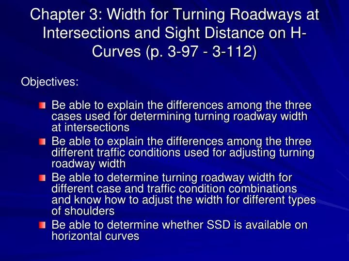
Chapter 3: Width for Turning Roadways at Intersections and Sight Distance on H-Curves (p. 3-97 - 3-112) • Be able to explain the differences among the three cases used for determining turning roadway width at intersections • Be able to explain the differences among the three different traffic conditions used for adjusting turning roadway width • Be able to determine turning roadway width for different case and traffic condition combinations and know how to adjust the width for different types of shoulders • Be able to determine whether SSD is available on horizontal curves Objectives:
Moark Junction RT roadways? Determine the width of the right turn roadway.
Width for Turning Roadways at Intersections (p.3-97) • The width of turning roadways at intersections are governed by the types of vehicles to be accommodated, the radius of curvature, and the expected speed. • The radius of curvature in combination with the track width of the design vehicle determine the width of a turning roadway. (Then, where does the expected speed come in for determining the width?)
3.3.11 Three Operational Cases of Turning Roadways • Case I: One-lane, one-way operation with no provision for passing a stalled vehicle Appropriate for minor turning movements and moderate turning volumes
Three Operational Cases of Turning Roadways (2) • Case II: One-lane, one-way operation with provision for passing a stalled vehicle Typical case for ramps and connections at channelized intersections. Note that the Case II widths for large design vehicles are large; hence Case I widths may be used if the number of large vehicles is low.
Three Operational Cases of Turning Roadways (3) • Case III: Two-lane operation, either one- or two-way
Case I and Case II Figure 3-21
Case III Figure 3-21
GB2011:Table 3-28B, p.3-101(Note: WB-50 does not exist in this table anymore)
Design Values (p.3-101 ~ 3.104) • Width values in Table 3-28B) are adjusted for various traffic conditions because practically no turning roadway will serve only one type of vehicle. So traffic condition factor is introduced. • Traffic condition A: Consists of predominantly of P vehicles, but some consideration is given to SU (SU-30) trucks • Traffic condition B: Sufficient SU (SU-30) trucks to govern design, but some consideration is given to tractor-semitrailer combination trucks. 5 to 10% trucks. • Traffic condition C: Sufficient tractor-semitrailer combination trucks, WB-40 or WB-50 (WB-40), to govern design. More trucks than condition B. The combination of letters, such as P-SU means that the design width in this example allows a P design vehicle to pass a stalled SU design truck or vice versa. Larger vehicles that can be accommodated by the widths meant for the combinations in the first table are shown in this table. Safety is maintained as long as they travel at lower speed and the drivers are more cautious and skilled.
+----- Tab. 3-29 Example (p.3-105): Case II and the traffic volume includes 10 to 12% trucks with an occasional large semitrailer combination for which Traffic Condition C is applicable. With a radius of 165 ft for the inner edge of the traveled way, what would be the width of this turning roadway? With a 4-ft stabilized shoulder? With a vertical curb?
Widths Outside Traveled Way (p.3-105) • The roadway width for a turning roadway includes the shoulders or equivalent lateral clearance outside the traveled way. • Within a channelized intersection, shoulders for turning roadways are usually unnecessary (often the lanes may be defined by curbs) • When there is a separate roadway for right turns, Its left edge defines one side of the triangular island when the turning radius is small. The side of the island may be defined by other delineators when the turning radius is large. Hence, a developed left shoulder is not necessary. • A shoulder usually provided on the right side of a right-turning roadway in rural areas. In urban areas, the right edge may be defined by curbs (because of low speeds). But recommended to avoid curbs near high-speed highways. • When a turning roadway has large curvature and length and away from other roadways, it is recommended to have a shoulder on both sides. Tab. 3-30
3.3.12 Sight Distance on Horizontal Curves (p.3-106) • Where there are sight obstructions on the inside of curves or the inside of the median lane on divided highways, a design may need adjustment in the normal highway cross section or change in the alignment if removal of the obstruction is impractical. • The sight line is a chord of the curve, and the stopping sight distance is measured along the centerline of the inside lane around the curve. ɵ Figure 3-23
2.75 ft for SSD 3.5 ft for PSD Criteria for Measuring Sight Distance • Height of driver’s eye • 3.5 ft from the pavement surface • Height of object • For SSD = 2.0 ft • For PSD = 3.5 ft • Sight obstructions • On horizontal curves the road surface on a crest curve, or something outside the traveled way, such as a longitudinal barrier, the backslope of a curve section, a tree, etc. Figure 3-22b
3.3.13 General Controls for Horizontal Alignment (p.3-111): Read this page carefully. • Alignment should be as directional as practical. • The minimum radius of curvature for that should be avoided wherever practical. • Consistent alignment should always be sought. Sharp curves should not be introduced at the ends of long tangents. • For small deflection angles, curves should be sufficiently long to avoid the appearance of a kink. • Sharp curvature should be avoided on long, high fills. • Caution should be exercised in the use of compound circular curves. • Abrupt reversals in alignment should be avoided. • The “broken-back” or “flat-back” arrangement of curves should be avoided unless absolutely needed. • To avoid the appearance of inconsistent distortion, the horizontal alignment should be coordinated carefully with the profile design. • Changing median widths on tangent alignment should be avoided, where practical, so as not to introduce a distorted appearance.
Do You Remember? Geometry of horizontal curves (Review what you learned in the survey class.)
Setting out of a simple horizontal curve Usually PI is given: • First find the station of PC Subtract T from the station of PI • Then find the next whole station from PC. Compute l1 to find 1. • Then find D for L = 100 ft • Then find the left over of the curve length l2 to determine the station of PT T You need the chord length to place stakes. l1 & l2are along the curve.