Download
1 / 12
130 likes | 485 Views
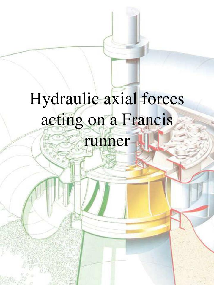
Hydraulic axial forces acting on a Francis runner. Hydraulic axial forces acting on a Francis runner. F 1 = Force from ring area F 2 = Reaction force from the absolute velocity at the inlet. F 3 = Force due to the outlet pressure

E N D
Hydraulic axial forces acting on a Francis runner F1 = Force from ring area F2 = Reaction force from the absolute velocity at the inlet. F3 = Force due to the outlet pressure F4 = Reaction force from the absolute velocity at the outlet. F5 = Force due to the pressure between the top cover and the impeller hub at the low pressure side of the labyrinth sealing. F6 = Force due to the pressure between the top cover and the impeller hub at the high pressure side of the labyrinth sealing. F7 = Force due to the pressure between the lower cover and the impeller ring at the high pressure side of the labyrinth sealing F8 = Force due to the pressure at the upper labyrinth sealing F9 = Force due to the pressure at the lower labyrinth sealing
Force due to the pressure between the top cover and the impeller hub at the low pressure side of the labyrinth sealing, F5. where: hp = pressure of the cooling water for the generator 25 meter water colomn hp will have another pressure if the water is not used for cooling. k = 0,50 – 0,55 rp = Dp/2 ri = Dr/2
Force due to the pressure between the top cover and the impeller hub at the high pressure side of the labyrinth sealing, F6.
Force due to the pressure between the lower cover and the impeller ring at the high pressure side of the labyrinth sealing, F7.
Force due to the pressure at the upper labyrinth sealing. F8. where the pressure at the high pressure side of the labyrinth sealing is:
Force due to the pressure at the lower labyrinth sealing. F9. where the pressure the high pressure side of the labyrinth sealing is: and hs = pressure head at the draft tube inlet