Download
1 / 34
640 likes | 2.84k Views
Beams: Pure Bending (4.1-4.5). MAE 314 – Solid Mechanics Yun Jing. Beams in Pure Bending. Prismatic beams subject to equal and opposite couples acting in the same plane are in pure bending. Pure vs. Non-Uniform Bending. Pure bending: Shear force (V) = 0 over the section

E N D
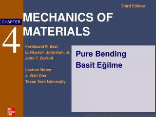
Beams: Pure Bending(4.1-4.5) MAE 314 – Solid Mechanics Yun Jing Beams: Pure Bending
Beams in Pure Bending • Prismatic beams subject to equal and opposite couples acting in the same plane are in pure bending. Beams: Pure Bending
Pure vs. Non-Uniform Bending • Pure bending: Shear force (V) = 0 over the section • Non-uniform bending: V ≠ 0 over the section Non-uniform bending • Moment → normal stresses • Shear force → shear stresses (Ch. 6) Pure bending• Moment →normal stresses Beams: Pure Bending
Pure Bending: Assumptions • Beam is symmetric about the x – y plane • All loads act in the x – y plane Beams: Pure Bending
Pure Bending: Curvature • Sections originally perpendicular to the axis of the member remain plane and perpendicular: “Plane sections remain plane.” • Sign convention • Positive bending moment:beam bends towards +y direction • Negative bending moment: beam bends towards -y direction Right angle Beams: Pure Bending
Pure Bending: Deformation • Since angles do not change(remain plane), there is noshear stress. • The top part of the beam contractsin the axial direction. • The bottom part of the beam expandsin the axial direction. • There exists a line in the beam thatremains the same length called theneutral line. • Set y = 0 at the neutral line. • ρ = radius of curvature • εx < 0 for y > 0 and εx > 0 for y < 0 Beams: Pure Bending
Pure Bending: Axial Strain • The length of DE is LDE = ρθ • The length of JK is LJK = (ρ-y)θ • Axial strain at a distance y fromthe neutral axis (εx): • Maximum compressive strain occurs on the upper surface. • Maximum tensile strain occurs on the lower surface. LJK LDE Beams: Pure Bending
Pure Bending: Axial Strain • c = maximum distance between the neutral axis and the upper or lower surface • When c is the distance to the surface in compression • When c is the distance to the surface in tension Beams: Pure Bending
Pure Bending: Transverse Strain • Recall there are no transverse stresses sincethe beam is free to move in the y and z directions. • However, transverse strains (in the y and zdirections) exist due to the Poisson’s ratioof the material. • ρ' = radius of anticlastic curvature = ρ/υ Beams: Pure Bending
Pure Bending: Normal Stress • Let us now assume that the beam is made of a linear-elastic material. • The normal stress varies linearly with the distance from the neutral surface. Beams: Pure Bending
Pure Bending: Normal Stress • Recollecting that the applied loading is a pure moment, we calculate resultant loads on the cross-section. • The resultant axial force must be equal to zero. …which is the definition of the centroid, so the neutral axis is just the centroid of the section. Beams: Pure Bending
Pure Bending: Normal Stress • The resultant moment about the z-axis must be equal to the applied moment M. Definition of the second moment of inertia, I Beams: Pure Bending
Example Problem A steel bar of 0.82.5-in. rectangular cross section is subjected to two equal and opposite couples acting in the vertical plane of symmetry of the bar. Determine the value of the bending moment M that causes the bar to yield. Assume m=36 ksi. Centroids and Moments of Inertia
Centroids and Moments of Inertia(A.1-A.5) MAE 314 – Solid Mechanics Yun Jing Centroids and Moments of Inertia
Review From Last Time • Beams in pure bending (no shear forces) • Plane sections remain plane • +M, upper surface in compression • +M, lower surface in tension • Transverse strains exist due to υ Radius of Curvature Neutral Line Centroids and Moments of Inertia
Centroids • To match with our axis convention use centroid in the y-direction. • Centroids for common shapes are located in the back cover of your textbook. • If a cross section shape has an axis of symmetry, then the centroid passes through that axis of symmetry. Centroids and Moments of Inertia
Centroids for Composite Shapes • Choose a reference x-axis (normally the base of the shape). • Divide the composite shape into individual shapes. • Calculate the area for each shape. • Find the location of the centroid for each shape relative to the reference x-axis. y h1b1 0.5h1 0.5h12b1 A1 h2b2 h1+0.5h2 h2b2(h1+0.5h2) A2 A3 h3b3 h1+h2+0.5h3 h3b3(h1+h2+0.5h3) x y=0 Centroids and Moments of Inertia
Moments of Inertia • Moment of inertia with respect to the x-axis • Moments of inertia for common shapes are located in the back cover of your textbook. x x x’ Ix x Ix Ix’ Ix Centroids and Moments of Inertia
Moments of Inertia for Composite Shapes • Divide the composite shape into individual shapes. • Calculate I of each shape about its own centroid. • Calculate I of each shape about the centroid of the entire composite shape using the parallel axis theorem: b1h13/12 b1h1d12 b1h1(d12+h12/12) A1 x’’’ b2h23/12 b2h2d22 b2h2(d22+h22/12) A2 A3 b3h33/12 b3h3d32 b3h3(d32+h32/12) x x’’ x’ Centroids and Moments of Inertia
Example Problem Find the location of the centroid and the moment of inertia of the section below (the moment is applied about the horizontal axis). 5 in 0.5 in 3 in 4 in 1.5 in 3 in Centroids and Moments of Inertia
Stress in the Elastic Range • Revisiting the beam subject to pure bending • For positive bending moment • Maximum tensile stress = Mc2 / I • Maximum compressive stress = Mc1 / I • For negative bending moment • Maximum tensile stress = Mc1 / I • Maximum compressive stress = Mc2 / I • The ratio I/c1 (or I/c2) is known as S, elastic section modulus. • Larger values for S indicate a beam that is more resistant to bending. c1 c2 Centroids and Moments of Inertia
Deformations in the Elastic Range • Which shapes are most resistant to bending? • S-beam • rectangular • Why? • Large portion of the cross section is located far from the neutral axis, resulting in large values of S. • The deformation of a member due to bending can be calculated by Centroids and Moments of Inertia
Example Problem A beam with cross-section like the previous example is subjected to a pure bending moment of M = -4500 in·lb. Find the maximum tensile and compressive normal stresses. 5 in 0.5 in 3 in 4 in 1.5 in 3 in Centroids and Moments of Inertia
Example Problem Knowing that the couple shown acts in a vertical plane, determine the stress at (a) point A, (b) point B. Centroids and Moments of Inertia
Example Problem The beam shown is made of nylon with an allowable stress of 24 MPa in tension and 30 Mpa in compression. Determine the largest couple M that can be applied to the beam. Centroids and Moments of Inertia
Example Problem Two vertical forces are applied to a beam of the cross section shown. Determine the maximum tensile and compressive stresses in portion BC of the beam. Centroids and Moments of Inertia
Bending in Composite Materials(4.6) MAE 314 – Solid Mechanics Yun Jing Centroids and Moments of Inertia
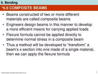
Normal Stress in Composite Materials • Strain is still the same as homogenous material because it is not dependent on material properties. • The stress distribution is no longer linear. • Use different material properties in each section. Centroids and Moments of Inertia
Normal Stress in Composite Materials • Top section: • Bottom section: Original Shape New Shape Centroids and Moments of Inertia
Bending in Composite Materials • The new “homogenous” beam produces the same response to bending as the composite beam. • We can now calculate the centroid and moment of inertia for this beam. • To calculate the axial stresses, use σx for material 1 and nσx for material 2. • Curvature of the composite member is Centroids and Moments of Inertia
Reinforced concrete beam • Beams are reinforced by steel rods • Concrete is very weak in tension, the steel rods will carry the entire tensile load • Concrete in the beam acts effectively only in compression Centroids and Moments of Inertia
Example Problem A bar having the cross section shown has been formed by securely bonding brass and aluminum stock. Determine the largest permissible bending moment when the composite bar is bent about a horizontal axis. Ea = 70 GPa, σall,a = 100 MPa, Eb = 105 GPa, σall,b = 160 MPa. Centroids and Moments of Inertia
Example Problem Knowing that the bending moment in the reinforced concrete beam is +100kip.ft and that the modulus of elasticity is 3.625106 psi for the concrete and 29 106 psi for the steel, determine (a) the stress in the steel, (b) the maximum stress in the concrete. Beams: Pure Bending 33
Example Problem A flitched beam consists of two 50mm×200mm wooden beams and a 12 mm×80mm steel plate. The plate is placed centrally between the wooden beams and recessed into each so that, when rigidly joined, the three units form a 100mm×200mm section as shown in the figure. Determine the bending moment the beam can withstand when the maximum bending stress in the timber is 12MN/m2. What will then be the maximum bending stress in the steel. (E for the timber is 10GPa, for steel is 120GPa) Beams: Pure Bending 34