Download
1 / 15
160 likes | 313 Views
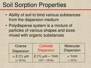
Planck Sorption Cooler Lifetime and Operational Options. Alfred Nash 9 May 2006 Jet Propulsion Laboratory. Outline. Definitions Basic Cooler Operating Principles Lifetime Limiters Worst Case Lifetime Regeneration Nominal Lifetime Options State Machine Things to Consider Q&A.

E N D
Planck Sorption Cooler Lifetimeand Operational Options Alfred Nash 9 May 2006 Jet Propulsion Laboratory
Outline • Definitions • Basic Cooler Operating Principles • Lifetime Limiters • Worst Case Lifetime • Regeneration • Nominal Lifetime Options • State Machine • Things to Consider • Q&A
Basic Cooler Operating PrinciplesCooling Power & Cold End Temperature • Cooling Power • Principle dependencies • mdot(∆P)∆H(∆P,TVG3) • 3rd V-Groove Temperature: TEMP_VG3 • Cooling Power Increases with Decreasing 3rd V-Groove Temp • Pressure • Desorption Power: POWER_DESORB • Does NOT depend on • Compressor Bed Switching Cycle Time: TIME_CYCLE • Not rate of compression • Cold End Temperature • Principle dependency • Warm Radiator Temperature: TEMP_RAD • Via Liquid/Vapor Pressure/Temperature Curve • Compressor absorption pressure sets cold end temperature (including line drop offset) • Weak dependency • Mass flow (pressure drop in line, absorption kinetics) • Does NOT depend on • 3rd V-Groove Temperature: TEMP_VG3
Desorb Desorb Absorb Absorb Absorb Absorb Basic Cooler Operating PrinciplesCooler Cycle Time • Compressor • Array of Elements, “T” with check valves into high and low pressure manifolds • High Pressure Manifold includes High Pressure Stabilization Tanks (HPSTs) - “Plenums” to smooth flow • Low Pressure Manifold includes Low Pressure Storage Bed (LPSB) where charge is stored at sub-atmospheric pressures prior to cooler activation • Compressor provides continuous refrigerant flow with minimized pressure ripple. • Six Beds Cycle Through Four Steps • Mounts on Service Module Radiator Panel • Decreasing Compressor Bed Switching Cycle Time: TIME_CYCLE does NOT increase mass flow Simplified 6 Bed Operation of Cooler 0-667 sec Heat Cool/ Absorb Absorb Absorb T t 667 - 1334 sec Cool/ Absorb Heat T t
Life Limiting Factors in Sorption Cooler Tdes • LaNi4.8Sn0.2Degradation (dotted lines) • Pressure for fixed temperature (achieved via power) decreases • Overcome by increasing desorption power • Capacity (flat width) decreases • Overcome with shorter cooler cycles • 8,300 cycles results in 80% BOL capacity • Recoverable by regeneration • High temperature, low pressure • Gas Gap • Rate of permeation from sorbent bed into annular (closed) gap exponential with sorbent bed temperature. • Temperature Pressure Cooling Power • 315 scc H2 capacity P Capacity/Cycle Tabs X
Worst Case Lifetime • For the purpose of this discussion, we define worst case to be: • Warm Radiator Temperature: TEMP_RAD: 262 K • 3rd V-Groove Temperature: TEMP_VG3: 60K • Combined Heat Lift Capacity from the Instrument Interfaces: HEAT_LIFT: 836 mW • Compressor Bed Cycle Time: TIME_CYCLE : 667s • Input Power Limit: 470 W • For the operating scenario communicated at SCS IQR Co-Location • “JPL and ESA (AH) will put together the benchmark scenario with these boundary conditions, including the details of the test durations per cooler at JPL, the expected test durations per cooler at CSL and taking into account the duration of 7.5 months per sky survey, 5 months to L2 and 2 month PV phase prior to operation. • Operational iterations can be made with respect to this benchmark”
Worst Case Lifetime • Using the values above, the following scenario was recommended for operations of FM1 and FM2, post delivery, assuming worst case interface conditions of 60 K 3rd V-Groove and 262 Warm Radiator for cooling of > 836 mW within an input power allocation of 470 W. • Operate FM1 for 25 days of testing at CSL, and performance of a “functional only” test of regeneration (no bed temperatures above 470K). • Actual was 8 days • Operate FM2 for ~10 days (including cool down of instruments) to confirm nominal cooler operation and perform steady state operation to allay any remaining concerns regarding potential further increases in input power. • Current plan is to operate FM2 for one month • Turn on FM2 for the last 20 days of the cruise phase to L2 • This duration chosen to provide ~ 10% lifetime margin at switchover • Operate FM2 for the 2 month PV Phase • Operate FM2 for the first sky survey (7.5 months) • Switchover from FM2 to FM1 (duration includes commissioning and cool down) • Operate FM1 for the second sky survey (7.5 months) • Worst Case is NOT very likely • CQM Testing, 3rd V-Groove Temperature: TEMP_VG3 < 50K • Warm radiator has “make up heater”
Worst Case Lifetime • Note: • FM2 was delivered with more lifetime, but requiring more input power, because it was regenerated at JPL prior to delivery • The planned functional test of regeneration of FM1 during AIV will NOT increase the input power requirements
Regeneration • The good news is • The LaNi4.8Sn0.2Hydride within the sorption cooler can be fully regenerated for degradations of 20% or less, in situ, by a high temperature (670 K), low pressure (1 atm) cooler “cycle” • Low dissipation into warm radiator. • The bad news is • The cooler was manufactured utilizing a high temperature bake out of the gas gaps of ~ 670 K, above the maximum expected operating temperature (475K) at the time of manufacture • 60W of methane parasitic is created in the gas gap during the first 2 hours of regeneration. • This is comparable to the BOL-EOL margin on power in the worst case • Diffusion of hydrogen into the gas gap during nominal operations limits the usefulness of regeneration in cases where the 3rd v-groove is colder than 60K.
Nominal Lifetime Options“The Derivative of Lifetime With Respect to Everything Else” • The Derivative of lifetime with respect to • Interface Parameters • 3rd V-Groove Temperature: TEMP_VG3 • <0 • Warm Radiator Temperature: TEMP_RAD • >0 • Performance Parameters • Combined Heat Lift Capacity from the Instrument Interfaces: HEAT_LIFT • <0 • Operational Parameters • Compressor Bed (switching) Cycle Time: TIME_CYCLE • Heat Up Power : POWER_HEATUP • <0 • Desorption Power: POWER_DESORB • Combined Heat Lift Capacity from the Instrument Interfaces: HEAT_LIFT • <0
Nominal Cases - First Estimates (FM2)(~ 30W less for FM1) Gas Gap Actuator Capacity 1 year 2 year 1 year Power Capability=514W 2 year 1 year 2 year 3 year Power Requirement=470W 3 year 1 year 4.3 year 2 year 3 year 2 year 3 year 4.3 year 1 year 2 year 1 year
State Machine • Why • To obtain rough order of magnitude (ROM) estimates of operational parameter or performance boundaries under various state conditions • To conduct trade studies of operational scenarios • What • It is • An Excel Workbook • Two modules • (Optimal) Operational parameters from performance desirements • Performance from operational parameters • It is NOT • An operations procedure generating machine • Lifetime calculator / optimizer • How • Matrix of linear equations built from separate analytic models connect inputs and outputs • NOT 100% ACCURATE • Who & Where • Developed by Al Nash at JPL • When • In development (first release in testing/review within JPL)
Things to Consider(A Partial List) • Cruise Phase • Duration • Turn On • Heat Lift • Cycle Time • PV Phase • Duration • Heat Lift • Cycle Time • Sky Surveys • Duration • Nominal Heat Lift for V-Groove < 60K • Cycle Time(s)
Q&A • Definitions • Basic Cooler Operating Principles • Lifetime Limiters • Worst Case Lifetime • Regeneration • Nominal Lifetime Options • State Machine • Things to Consider