Download
1 / 37
370 likes | 509 Views
Status of ELM trigger investigations on JET and AUG R. Wenninger IPP Garching, EFDA JET. Outline. Pellet technology at AUG and JET Pellets – a candidate ELM mitigation method Observation of pellet triggered ELMs in H-mode regimes Direct pellet driven MHD

E N D
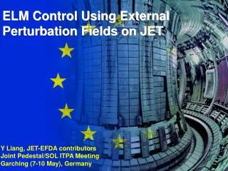
Status of ELM trigger investigations on JET and AUG R. Wenninger IPP Garching, EFDA JET
Outline • Pellet technology at AUG and JET • Pellets – a candidate ELM mitigation method • Observation of pellet triggered ELMs in H-mode regimes • Direct pellet driven MHD • Careful considerations towards trigger mechanism • Pellet impact on tokamak (ITER) operation • Summary
Outline • Pellet technology at AUG and JET • Pellets – a candidate ELM mitigation method • Observation of pellet triggered ELMs in H-mode regimes • Direct pellet driven MHD • Careful considerations towards trigger mechanism • Pellet impact on tokamak (ITER) operation • Summary
AUG Pellet Centrifuge AUG fuelling system Volume to freeze and compress ice Extrusion nozzel Extrusion arm (s=0.25mm) Cutter VHFS
AUG Blower Gun AUG pacing system • High frequency: Up to 143Hz • 2nd injection line for tangential transfer through edge plasma close in or outside separatrix
JET – High Frequency Pellet Injector High Frequency Pellet Injector (HFPI): • Worldwide 1st system fully optimised for ELM pacing • Deep fuelling also possible PELIN pellet injector
V H L JET – Overall Pellet system • Injection from 3 poloidal locations • Centrifuge – Future option for parallel fuelling and pacing Pellet Injection Locations
JET – HFPI Injection capabilities Values from HFPI specification
Outline • Pellet technology at AUG and JET • Pellets – a candidate ELM mitigation method • Observation of pellet triggered ELMs in H-mode regimes • Direct pellet driven MHD • Careful considerations towards trigger mechanism • Pellet impact on tokamak (ITER) operation • Summary
Reliable ELM control technology mandatory for ITER ELM control – a necessary requirement • Acceptable ELM size for ITER: • Target plate erosion negligible at 0.5MJ/m2 for CFC and W (Zhitlukhin 2007) • Assume strong asymmetry of deposition on inner/outer targets: Pout/Pin = 1 : 2 • Tolerable energy deposition on target plates per ELM: WELM,target=0.5MJ/m2 1.3m2 (1+1/2) 1MJ (Polevoi EPS 2008) • WELM,target fELM = Psep, = 0.2 – 0.4(Herrmann 2002) • fELM = 20 – 40Hz (spont. ~ 2 - 4Hz) F. Federici et al PPCF 45 (2003)
ELM control technologies • Edge ergodisation by resonant magnetic perturbation (Y. Liang PRL 98 (2007)) Plasma edge rarefaction without cooling (needs pellet fuelling) • Magnetic ELM pacing by vertical kicks – accelerating plasma in vertical direction (Sartori et al.) • Impurity seeding Type III (higher frequency) + higher radiation fraction • Pellet ELM Pacing (P. Lang NF 2004) • … DIIID None of these technologies is yet proven to work at ITER
Pellet ELM Pacing – Proof of Principle at AUG AUG JET • fELM≥ fPEL fELM more than doubled at AUG • WELMfELM=const at const. Pheat confirmed for pellet triggered ELMs (Lang NF 2002)
Scaling aspects: size, magnitude, location of required perturbation? • Local perturbation imposed by pellet particle deposition is strong enough for triggering ELMs at AUG and JET (Until now every pellet injected into ELMy regime triggered an ELM) • But does this still hold at ITER size? • More physics understanding necessary! • Threshold might be defined by • local (e.g =T, n, p, j,...) and • relative extension (e.g. x/R) x Readjustment might be possible but at the expense of again stronger fuelling (and pumping) and hence convective losses.
Outline • Pellet technology at AUG and JET • Pellets – a candidate ELM mitigation method • Observation of pellet triggered ELMs in H-mode regimes • Direct pellet driven MHD • Careful considerations towards trigger mechanism • Pellet impact on tokamak (ITER) operation • Summary
Pellet can trigger an ELM at any time between Type-I ELMs • ELMs triggered by with feff up to 350Hz (temporal resolution problem in higher frequency) • Triggered ELM: 50s delay between pellet causes perturbation and ELM AUG G. Kocsis
Quiescent H-Mode: Pellets don’t trigger ELMs in any H-mode regime AUG • QH: Obtained by counter injection • Good confinement (H98y~1) • High pedestal and core ion temp. • ELMs replaced by ‘edge harmonic oscillation’ (EHO, ~10kHz) + ‘high frequency oscillation’ (300 – 400kHz) • Even large pellets do not trigger ELMs
Pellet can terminate phase free of spontaneous ELMS • Pellets trigger first ELM ~0.5s earlier than first spont. ELM occurs in reference shot • Avoid spontaneous Giant ELM (e.g. 1st after ELM free phase) • Each pellet triggered an ELM of smaller size, with <20% the loss in energy, than the spontaneous Giant ELM JET 14MW NBI
Pellets lead to fastest ELM-growth (I) AUG Comparison of growth time of MHD signal up to its max. value (ELM rise time): spontaneous Type I pellet driven between Type I pellet driven between Type III < spontaneous Type III
Pellets lead to fastest ELM-growth (II) AUG Type III Rad. cooled Type I Type I • ELM rise time of pellet driven ELMs const. ( spont. Type I: fastest growth) • ELM rise time increases from Type I, via rad. cooled Type I to Type III • Correlated e.g. with parallel resistivity at pedestal top
Outline • Pellet technology at AUG and JET • Pellets – a candidate ELM mitigation method • Observation of pellet triggered ELMs in H-mode regimes • Direct pellet driven MHD • Careful considerations towards trigger mechanism • Pellet impact on tokamak (ITER) operation • Summary
Option 2: Direct pellet driven MHD Perturbation of plasma parameters (n, T, j,...) ELM Pellet Simplistic causal model Option 1: Perturbation of plasma parameters (n, T, j,...) Direct pellet driven MHD ELM Pellet
Magnitude of required ELM trigger perturbation: Tiny in pellet terms? Magnetic signal for pellet driven ELMs can be separated in • ELM related MHD • Directly pellet driven part • observed even in L-mode • stops abrupt with burn out • @ trigger time below resolution • Direct pellet driven MHD sufficient, if threshold would be > x100, if option 1 JET
≈ 50 µs OH: Direct pellet driven MHD only • Ohmic plasma (OH) Only direct pellet driven component AUG • Faintest pellet provokes stronger MHD than at typical ELM onset
OH: No sign. Variation of directly pellet driven MHD with pellet parameters • Repeated use of same stationary scenario • Averaging of amplitude of dB/dt (MHD) over entireshot for all pellets (about 10) AUG • MHD clearly correlated to radial position of pellet and thus on local plasma parameters (e.g. p, j, Te, …) • No significant dependence on pellet parameters (mass, velocity) and thus on ablation / deposition saturation effect? • Pellet driven MHD depends mainly on plasma parameters
Outline • Pellet technology at AUG and JET • Pellets – a candidate ELM mitigation method • Observation of pellet triggered ELMs in H-mode regimes • Direct pellet driven MHD • Careful considerations towards trigger mechanism • Pellet impact on tokamak (ITER) operation • Summary
Spont. type I and triggered ELMs – No significant difference on level of density fluctuation • Reflectometry at fixed frequency mode density fluctuation • Compare frequency power spectra (Integration: 2.5ms) for • 3 different densities • LFS and HFS • Spontaneous and triggered ELMS • No significant difference between spontaneous type I and triggered ELMs AUG
Spont. type I and triggered ELMs – No significant difference in target power load pattern AUG • Infrared Thermography: • Observation of type I ELMs reveals non-axissymmetric stripes on divertor targets mapped to filaments (Eich PRL 2003) • For later ELM phase mode structure can be identified • No significant difference in patterns between spontaneous type I and triggered ELM
J a Pellets in the Peeling-Ballooning-Picture • PB-Theory quantifies ELM dynamics via growth Rate of driving mode • Type I ELM cycle (Connor 1998) • Type I ELMs: • Typical av. inter ELM time > ms • Pellet triggered ELMs: • t(pellet at location – ELM) < 0.1ms • If there is a similarity in the mechanism, pellet must shortcut the type I ELM cycle significantly Instable >C Resistive time scale Stable <C Transport time scale
Outline • Pellet technology at AUG and JET • Pellets – a candidate ELM mitigation method • Observation of pellet triggered ELMs in H-mode regimes • Direct pellet driven MHD • Careful considerations towards trigger mechanism • Pellet impact on tokamak (ITER) operation • Summary
Pellet impact on tokamak (ITER) operation – Penetration depth and required pellet mass • Cumulative distribution function of trigger locations ~100% at ped. top • Assumption: Pellet penetration to pedestal top is required • Pellet mass required to reach pedestal top for different scenarios: • Reference: width 20cm, Te at top 4keV • Wide pedestal: width 30cm, Te at top 4keV • High pedestal: width 20cm, Te at top 5keV • Lower speed More mass required but stronger perturbation • Assumption: Ref. scenario Kocsis 2007 ITER K.Gál (Hybrid-LLL-Code)
X ? ITER total pumping rate: 40 – 50 1021 D/s Results from Hybrid-LLL code Assuming 40Hz pellet frequency Pellet impact on tokamak (ITER) operation – 3 injection scenarios
Pellet impact on tokamak (ITER) operation – Convective power losses due to pellets • Pellet particles are heated by the plasma up to 75% Tped,ref • Steady state cond.: Pellet = add. loss • Padd. loss= 3 Pellet kB <T> • Assuming <T>=3keV (75% Tped,ref) • Padd. loss 200MW (P) • 60MW (OS) • 6MW (AO) ITER total heating power: 40MW • Conclusion: • Self-consistent modeling of the localized particle deposition and enhanced transport required for more robust figures • At least OS is needed – better AO
A new idea – Beryllium pellet injection • Advanced Optimistic: 1000m/s of 1020D (1.6mm3) extremely challenging • High speed should be easier for Be pellet (melting point 1278°C, crystal structure) • Simulation with a C pellet (K.Gál) indicate 1 * 1019 Be (a Ø 500μm sphere) would be sufficient to reach pedestal top • Fuel dilution: Taking a plasma particle content of 1023e, P=1s, finjection=40Hz : • ΓP ≈ 4 * 1020/s Be, but ≈ 4 * 1021/s expected from wall • Need to demonstrate: • - ELM triggering by a Be pellet • - Pellet transfer through a tube ITPA Activity
Summary • JET-HFPI: Milestone in development of pellet injector technology • Pellet ELM Pacing: Candidate technique for ITER ELM control • So far every pellet injected into ELMy regime triggered an ELM – not clear, if this holds for ITER • Pellet can trigger an ELM at any time between Type-I ELMs • Pellet triggered ELMs grow as fast as the fastest spontaneous ELMs (Type I) • Pellet driven MHD depends mainly on plasma parameters • If there is a similarity in the mechanism, pellet must shortcut the type I ELM cycle significantly • 500 or 1000m/s injection mandatory for tolerable pump load and additional power losses in ITER