Download
1 / 27
270 likes | 446 Views
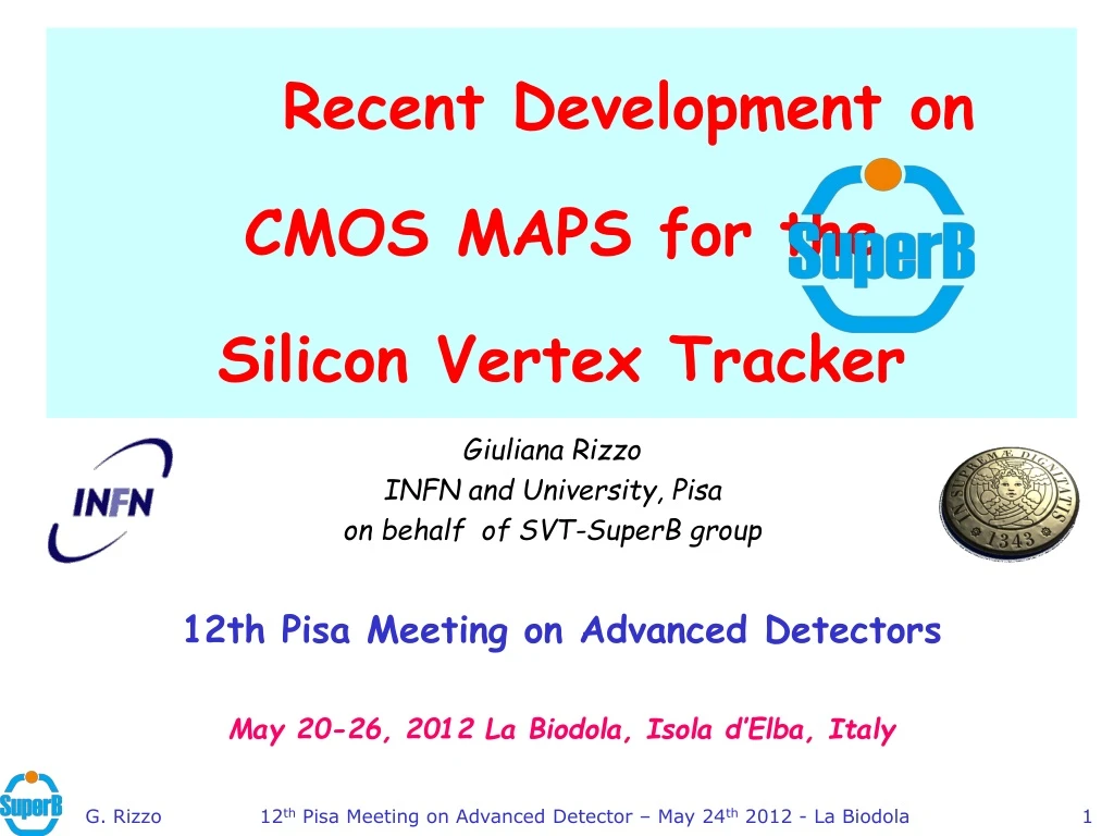
Recent Development on CMOS MAPS for the Silicon Vertex Tracker. Giuliana Rizzo INFN and University , Pisa on behalf of SVT- SuperB group. 12th Pisa Meeting on Advanced Detectors May 20-26, 2012 La Biodola , Isola d’Elba , Italy. Outline. To be updated.

E N D
Recent Development on CMOS MAPS for the Silicon Vertex Tracker Giuliana Rizzo INFN and University, Pisa on behalf of SVT-SuperBgroup 12th Pisa Meeting on Advanced Detectors May 20-26, 2012 La Biodola, Isolad’Elba, Italy 12th Pisa Meeting on Advanced Detector – May 24th 2012 - La Biodola
Outline To be updated • The SuperB Project Status • The Silicon Vertex Tracker & Layer0 • CMOS MAPS options for Layer0 upgrade • DNW MAPS achieved performance • 3D MAPS with vertical integration • 2D MAPS with quadruple well process • Conclusions 12th Pisa Meeting on Advanced Detector – May 24th 2012 - La Biodola
The SuperB Project To be updated • The physics case for a high luminosity B Factory is clearly established. • Flavour physics is rich, promises sensitivity to New Physics ... but large statistics (50-100 ab-1) is needed • First generation of B-Factories (PEP-II and KEKB) exceeded their design goals (L~1.2-1.7 x1034 cm-2 s-1 , integrated 1.2 ab-1) but an upgrade of ~2 orders of magnitude in Lis needed to get 50ab-1 . • Increasing Luminosity by brute-force (higher currents) is expensive and difficult • wall plug power and detector background explosion • effective limitation around 5x1035 cm-2 s-1 • The SuperB italian accelerator concept allows to reach L =1036 cm-2 s-1with moderate beam current (2A) using very small beam size (~1/100 of present B-Factories beams exploiting the ILC R&D on damping rings & final focus) with the help of the Crab Waist scheme at the IP to keep the beams small & stable after collision (verified with tests on Dafne) • This approach allows to (re-) use parts of existing detectors and machine components. 12th Pisa Meeting on Advanced Detector – May 24th 2012 - La Biodola
The SuperB Process NEXT STEPS Government approval expected very soon Technical Design Report: summer 2011 Operation by 2015. To be updated • SuperB Conceptual Design Report published in 2007 • All scientific reviews are positive. Presented to CERN Council and approved for preparatory phase. • Growing international interest and participation with formal international collaboration being formed. Project structure defined. • MOUs signed with France, Russia and SLAC and a letter of support from Canada. • Technical Design Report phase approved by INFN in 2009 • R&D is proceeding on various items (eg. SVT Layer0) • Intermediate Progress Report published this summer • http://arxiv.org/abs/1007.4241 • SuperB inserted as first project in the National Research Plan by the Italian Research Ministry 12th Pisa Meeting on Advanced Detector – May 24th 2012 - La Biodola
The SuperB Silicon Vertex Tracker The SVT provides precise tracking and vertex reconstruction, crucial for time dependent measurements. BaBar SVT • 5 Layers of double-sided Si strip sensor • Low-mass design. (Pt < 2.7 GeV) • Stand-alone tracking for slow particles. • 97% reconstruction efficiency • Resolution ~15μm at normal incidence SuperBSVT based on Babar SVT design for R>3cm. BUT: 1) reduced beam energy asymmetry (7x4 GeV vs. 9x3.1 GeV) requires an improvedvertex resolution (~factor 2) • Layer0 very close to IP(@1.5 cm) with low material budget (<1% X0) and fine granularity (50 mm pitch) • Layer0 area 100 cm2 2)bkg levels depend steeply on radius • Layer0 needs to be fast and rad hard hit rate 20 MHz/cm2, TID 3 MRad/yr, eq. neutron fluence 7 x 10¹² n/cm2/yr • x5 safety factor to be inlcuded!
SuperB SVT Layer 0 technology options MAPS and 3D verticallyintegratedpixelsare the twomostadvancedoptionsconsidered for Layer0 upgrade: Complexity Digital tier Analog tier Sensor Wafer bonding & electrical interconn. To be updated • Striplets option:mature technology, not so robust against background occupancy. • Marginal with back. rate > 100 MHz/cm2 • Moderate R&D needed on FE chip module interconnection/mechanics • Hybrid Pixel option:viable, slightly marginal. • Reduction of total material at 1%X0 doable. • Reduction of front-end pitch to 50x50 μm2 Produced and tested FE prototype chip with 50x50 μm2 pitch & fast data push readout (already developed for DNW MAPS) - (4k pixels, ST 130 nm) • CMOS MAPS option:new & challenging technology. • Sensor & readout in 50 μm thick chip! • Extensive R&D (SLIM5-INFN Collaboration) on • Deep N-well devices 50x50μm2 with in-pixel sparsification. • Fast readout architecture implemented • CMOS MAPS (4k pixels) successfully tested with beams. • Thin pixels with Vertical Integration: reduction of material and improved performance. • Two options are being pursued (VIPIX – INFN Collab.) • DNW MAPS with 2 tiers • Hybrid Pixel: FE chip with 2 tiers + high resistivity sensor 12th Pisa Meeting on Advanced Detector – May 24th 2012 - La Biodola
Deep Nwell (DNW) sensor concept SHAPER DISC LATCH PREAMPL Newapproach in CMOS MAPS design compatible with data sparsification architecture to improve readout speed potential Developed in a 130 nm CMOS process, various different chips successfully tested with radioactive sources and beam A classical optimum signal processing chain for capacitive detectors can be implemented at pixel level: • Charge-to-Voltage conversion done by the charge preamplifier • The collecting electrode (Deep N-Well) can be extended to obtain higher single pixel collected charge (the gain does NOT depend on the sensor capacitance), reducing charge loss due to competitive N-wells where PMOSFETs are located • Need to keep the fill factor (DNW/tot N-well )as high as possible: ~ 90% in our design. 12th Pisa Meeting on Advanced Detector – May 24th 2012 - La Biodola • 7
Latest 2D generation of DNW MAPS: APSEL4D 32x128 pix - 50 mm pitch perif & spars logic MP 4x4 pixels Data lines in common 2 MP private lines Column enable lines in common Data out bus Periphery readout logic In the active sensor area we minimized: • logical blocks with PMOS to reduce the area of competitive n-wells • digital lines for point to point connections to allow scalability of the architecture with matrix dimensions • 4K(32x128) 50x50 μm2 matrix subdivided in MacroPixel (MP=4x4) with point to point connection to the periphery readout logic: • Register hit MP & store timestamp • Enable MP readout • Receive, sparsify, format data to output bus S/N ~ 20 with power consumption ~ 30 mW/ch Signal for MIP (MPV) =980e- 90Sr electrons S/N=23 mV Landau Cluster signal (mV) Noise events Threshold dispersion = 60 e- Gain = 860 mV/fC 12th Pisa Meeting on Advanced Detector – May 24th 2012 - La Biodola
Evolution of DNW MAPS To be updated DNW MAPS efficiency 92%: competitive N-wells (PMOS) in pixel cell steal charge reducing the hit efficiency: fill factor (DNW/tot N-well) ~ 90 % Charge collection efficiency main limitation of DNW MAPS for application in Layer0: Area of competiveNwellincreses with more complex in-pixel logic (fast readout needed) Charge collection further reduced by radiation damage Two approaches to improve MAPS performance • 3D MAPS: (2 tiers for sensor&analog + digital) • fill factor and efficiency can improves significantly. • 2D MAPS with INMAPS 180 nm process • 4th well (deep Pwell), below competitive Nwells, used to avoid parassitic charge collection • high-Wepilayeralsoavailablefor improvedchargecollection and radiationhardness! 12th Pisa Meeting on Advanced Detector – May 24th 2012 - La Biodola
Evolving from 2D to 3D MAPS 3D integration of 2 CMOS layers 2D CMOS technology The use of vertical integration (2 CMOS layers interconnected) can improve MAPS performance • higher sensor efficiency (PMOS in competitive N-wells removed from the sensing layer) • deep N-well area can be reduced (lower CD better noise/power trade-off) • more advanced readout architecture can be integrated on pixel • an extra high res. substrate can be used as pixel sensor and connected First APSEL-like DNW MAPS (2 tiers) realizedwithin the 3DIC Consortium to explore the 130 nm Chartered/Tezzaronprocess. • Several problems with 3D interconnection (bad alignment …) • While still waiting for good 3D chips: • test of the sensor+analoglayer confirmed the expected improvemente in collection efficiency • prepare new 3D run Tezzaron/GlobalFoundries technology (organized by CMP/MOSIS) Chartered/Tezzaron technology (Fermilab MPW run) • 10
Digital layer Tests of the layer with sensing electrode and analog front-endin first 3D APSEL chips digital Fe55 g (5.9 keV) – 3x3 matrix Lab Tests ENC = 45e- Gain = 300 mV/fC Sensor + analog Sensor + analog Beam test @ CERN Efficiency vsthr. on pixel seed Cluster signal-hits on track Preliminary Efficiency > 98% thanks to reduced PMOS N-wells in the pixel cell with 3D 7x s_noise Noise events==off time S/N=23 MPV=1044 e- Gain =320 mV/fC (Fe55) Noise events==off time window (w.r.t. scintillator) PH seed cut e-]
Design featuresfor next 3D devices 3D Apsel • In the next 3D run (Tezzaron/GlobalFoundries) two pixel chips for SuperB Layer0 application: • 3D APSEL larger CMOS MAPS matrix (128x100) • Superpix1 FE chip for hybrid det. (128x32) • Both chips share a new readout architecture flexible: : data push & triggered version) Superpix1 3D Apsel 12 12th Pisa Meeting on Advanced Detector – May 24th 2012 - La Biodola
Readoutarchitecture in the pixel cell: time-stamp latch and comparator for a time-orderedtriggeredreadout In-pixel logic for a time-ordered readout Complex in-pixel logic can be implemented without reducing the pixel collection efficiency; readout can be data push or triggered (only selected time stamps are read out). Timestamp (TS) is broadcast to pixels and each pixel latches the current TS when fires. Matrix readout is TS ordered • A readout TS enters the pixel and an HIT-OR-OUT is generated for columns with hits associated to that TS • A column is read only if HIT-OR-OUT=1 • DATA_OUT is generated for pixels in the active columns with hits associated to that TS. • 13 12th Pisa Meeting on Advanced Detector – May 24th 2012 - La Biodola
New Pixel Readout Architecture Features 1 Matrix • In-pixelHit & Time Stamp Latch • TS request to the matrix • Pixel FastOR activates IFlatched TS == requested TS • Cascaded column FastORs • 1 columnsparsified in 1 clk cycle (whatever the occupancy ) • Only active-FastOR columns are enabled in sequence.(i.e. 10 active column FastORs 10 clk cycles readout) • Triggered and Data-Push mode. • Implemented in our last INMAPS submission & ready for next 3D submissions 1 2 3 Requesting TS: 1 0 2 0 3 1 Encoding & DequeuingSystem 0 1 3 Simulations DO NOTtake into account: SensorEfficiency. Analog FE. 0 2 3 DATA PUSH MODE TRIGGERED MODE Pixel latchesaslatencybuffers 98.2% Active Column Expected working condition • 130 MHz hit rate. • 192x256 matrix • 50 MHz read clock • 2.5 MHz trigger rate (stressed condition) • 200k events per point 130 MHzhit rate. 12th Pisa Meeting on Advanced Detector – May 24th 2012 - La Biodola
INMAPS developments for SuperB Layer0 • Small N-well collecting diodes with small input capacitance and low power consumption. • The forth-wellpreventschargestealing by the parasiticN-wells (efficiency benefit). • Sameanalog and digitalarchitectureas APSEL chips, to fit at best the high background rate of Layer0. 3x3 analog matrices with different diodes configurations 32x32 matrix with sparsified digital readout architecture INMAPS Chip (5x5 mm2) First chips under test now 12th Pisa Meeting on Advanced Detector – May 24th 2012 - La Biodola
INMAPS CELL 1.5 x 1.5 mm2 See S. Zucca’s poster for more details on analog design 12th Pisa Meeting on Advanced Detector – May 24th 2012 - La Biodola
INMAPS RESULTS: 3x3 analog matrix Preliminary • Response to radioactive source • 55Fe g: 5.9keV foto peak hardly visible due to very small diode area. • Charge totally collected for g interaction in the depleted volume below the diode. Partial collection elsewhere. End point (5.9 keV + 3 s noise) used for gain evaluation (agreement within 10% with Cinj) • 90Sr e- signal cluster: MPV ~ 300 e-, compatible with 5 um epi layer of first chips chips with 12 um epi layer (standard & high resistivity) available in June. 90Sr e- - Chip1 5 mm epi layer 55Fe g – Chip1 Noise and gain measured in 3x3 analog matrix in good agreement with PLS: • ENC = 30 e- (~20% dispersion) • Gain=920 mV/fC (~10% dispersion) 12th Pisa Meeting on Advanced Detector – May 24th 2012 - La Biodola Pixel signal (mV) Cluster signal (mV)
INMAPS 32x32 digital matrix (I) Preliminary • Noise and gain measured in pixels with Cinj and analog output • ENC = 30 e- gain=680 mV/fC Maybe Insert plot with gain for 32x32 chip 2 V vs Q e- vrif_mirbassa • Threshold dispersion = 7mV (~ 2 xs_noise ) • Noise (+gain) dispersion ~ 35-40% • Further tests to evaluate gain dispersion with Fe55 end point ongoing. Baseline – Chip3 • Few dead pixels: ~ 0.3% (on 3 chips 32x32) Noise hits – Chip3 Sr90 hits – Chip1 Threshold and noise dispersion inside matrix measured with noise scans (occupancy vs discriminator threshold) 12th Pisa Meeting on Advanced Detector – May 24th 2012 - La Biodola
INMAPS 32x32 digital matrix (II) Preliminary • Threshold scans similar in both operation modes. + data push + triggered • Triggered mode also verified with specific test retrieving data injected at selected TS. • Pulse injection @ TS = 0 high threshold no noise hits above threshold • Trigger arrives @ TS =2 with trigger latency setting = 3 TS triggered event TS = 0 • Data out stream info: • TS =0: 0 pixels in submatrix0 • TS =0: 1 fired pixel in submatrix1 Standard functionality of new readout architecture verified in the two operation modes available on chip: data push (all TS readout) and triggered (only selected TS readout). 12th Pisa Meeting on Advanced Detector – May 24th 2012 - La Biodola
Investigating a discriminator problem • During investigation discovered that for small signal injected (and seen with the analog output) no hit registred by the discriminator • no change in the 50% turn on THR w.r.t. THR without injection • This problem was tracked with a “slow” turn on of the discriminator that prevent signals to be seen if the Time over Threshold (TOT) is too small. • Fix implemented: increase the discharge time of the analog signal to increase the TOT and allow the “slow” discriminator to fire • Not optimal for fast operation! Larger TOT for slow discharging signal • Now investigating more carefully the design to understand the origin of the problem (reproduced in simulation with some corner process parameters) and implement a more robust design of the discriminator for next chips During initial tests: noise and injection scans look strange for small signal. 12th Pisa Meeting on Advanced Detector – May 24th 2012 - La Biodola
Conclusions 12th Pisa Meeting on Advanced Detector – May 24th 2012 - La Biodola
backup 12th Pisa Meeting on Advanced Detector – May 24th 2012 - La Biodola
Investigating a discriminator problem (I) Preliminary • Noise lower than the one measured with analog output and turn on curve very narrow and strongly asymmetric. • For small signal injected (and seen with the analog output) no hit registred by the discriminator no change in the 50% turn on THR w.r.t. THR without injection • Gain measured with the 50% turn point (THR 50% in red in the plot) vs. Q injected underestimated w.r.t to gain measured using the analog output (in blue). During initial tests noise and injection scans (channel with Cinj available) looked strange for small signal. 12th Pisa Meeting on Advanced Detector – May 24th 2012 - La Biodola
Investigating a discriminator problem (II) • This problem was tracked with a “slow” turn on of the discriminator that prevent signals to be seen if the Time over Threshold (TOT) is too small. • Fix implemented: increase the discharge time of the analog signal to increase the TOT and allow the “slow” discriminator to fire • Not optimal for fast operation! • Injection scans now OK: gain measured with analog output and with 50% turn on THR agree! • Show old vs new plot • For THR close to signal peak TOT is still too small for the slow discriminator to be seen (~1-2 mV overdrive from simple analytical calculation) noise from threshold scan still underestimated by ~this amount. Need a proper simulation to quantify this effect. Larger TOT for slow discharging signal • Now investigating more carefully the design to understand the origin of the problem (reproduced in simulation with some corner process parameters) and implement a more robust design of the discriminator for next chips 12th Pisa Meeting on Advanced Detector – May 24th 2012 - La Biodola
Tesbeam with irradiated MAPS - 2009 July 2009 CERN Testbeam Results for MAPS (3x3 matrix) with analog output (pre/post irrad. 10 Mrad 60Co ) • Qcluster ~1040 e- for M1 (930 e- for M2) • S/N~15-20 depending on the electrode geometry • Efficiency~90% for both M1,2 in agreement with the measurements on digital MAPS • Modest reduction in collected charge and efficiency in chip irradiated up to 10 Mrad • ENC increased by ~35% apsel3T1 M1 - 3x3 cluster signal 120 Gev pions - after 10 Mrad M1 - chip 8 not irradiated M1 chip 24 @ 10 Mrad THR < 4 s Noise Efficiency S = 1003 e- Thr. e- G.Rizzo – Pixel 2010 – Grindelwald - CH
Exploiting 3D integration: pixel pitch and sensor efficiency 40 mm Parasitic N-wells Main design features and simulation results A three-dimensional technology makes it possible to significantly reduce the area of charge stealing N-wells significant improvement in charge collection efficiency expected W/L=30/0.3 CD=250 fF ~1 ms peaking time Charge sensitivity: 750 mV/fC Equivalent noise charge (ENC): 33 e rms Threshold dispersion: 40 e rms Collecting electrode Sensor area: 346mm2 NW-PMOS area: 22mm2 Fill Factor: 0.94 (0.87 in the “2D” version) G.Rizzo – Pixel 2010 – Grindelwald - CH
Readout electronics in a 40 x 40 mm2 3D MAPS pixel cell Sensing diode and charge sensitive preamplifier TIER 2 (TOP) Pixel-level digital front end discriminator AVDD AVDD DVDD Inter-tier bond pads Vfbk Vt DGND Digital readout electronics CF AGND Pixel-level sparsification logic 3D integration removes layout constraints and will allow for an improved readout architecture (no macropixel) in future chips TIER 1 (BOTTOM) from the discriminator 8x32 pixel matrix N-well G.Rizzo – Pixel 2010 – Grindelwald - CH