Download
1 / 58
580 likes | 731 Views
ITEC 3010 “Systems Analysis and Design, I” LECTURE 7: The Object-Oriented Approach to Requirements. [ Prof. Peter Khaiter ]. Lecture Outline. Unified Modeling Language (UML) Object-Oriented Requirements (OOR) System Activities Use Case Diagram Activity Diagram System Sequence Diagram

E N D
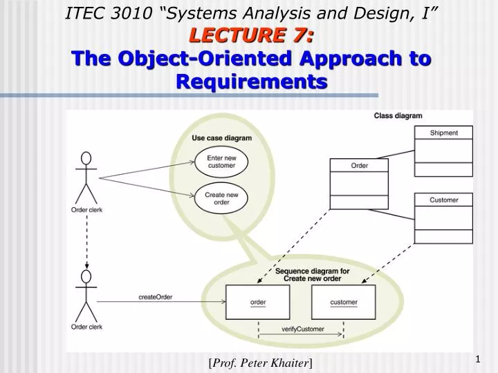
ITEC 3010 “Systems Analysis and Design, I” LECTURE 7: The Object-Oriented Approach to Requirements [Prof. Peter Khaiter]
Lecture Outline • Unified Modeling Language (UML) • Object-Oriented Requirements (OOR) • System Activities • Use Case Diagram • Activity Diagram • System Sequence Diagram • State Machine Diagram • Integrating Object-Oriented Models
Unified Modeling Language (UML) • OOA considers an IS as a set of objects that work together to carry out the function. OO analysis involves two steps: (1) Definition the set of objects that will make up the system and describing the interactions or communications among the various objects (these interactions take the form of messages between objects) (2) Describing the internal processes that go on within each object to respond to messages from other objects, and to initiate messages to other objects • UML is a notation used in OO modeling • A preliminary version of UML was presented in 1995 • In 1997 UML was presented to the Object Management Group (OMG) as a standard modeling technique • OMG (est. 1989) is a consortium of software vendors, developers and organization with the goal to provide a common architectural framework for OO applications – www.omg.org
Object-Oriented Requirements (OOR) • Object-oriented system requirements are specified and documented through process of building models • Modeling process starts with identification of use cases and problem domain classes (things in users’ work environment) • Business events trigger elementary business processes (EBP) that new system must address as use cases • Use cases define functional requirements
OOR - Models OO models (or diagrams) to define system requirements are called use case models: •Use case diagram shows the various user roles and how they will use the system. It is an extension of the event table. It is a convenient way to document the function that the system must support. •Sequence diagram shows inputs and outputs and sequence of messages between an external actor and the system objects during a use case or scenario. • The flow of information between the objects is in form of messages OO models (or diagrams) to define classes of objects and their states are called domain models : •Domain class diagram (see lecture 5) – identifies and classifies the objects that will make up the new system along with their properties (or attributes) •State machine diagram describes the states and behavior of each object: life of an object in state and transitions
The System Activities—A Use Case/Scenario View • Use case model used to identify and define all elementary business processes that system must support • Use cases are identified at two levels: • Overview level (event table and use case diagram of all the use cases) • Detailed level (for each use case – use case description, activity diagram, sequence diagram) • Use case – an activity a system carried out, usually in response to a user request • Actor (person, other system, or device that receive services from the system and who actually interact with the system) • Role played by user • Outside automation boundary
Techniques for Identifying Use Cases (Review from Chapter 5) • Identify user goals • Each goal at the elementary business process (EBP) level is a use case • EBP – task performed by one user in one place and in response to business event that adds measurable business value, and leaves system and data in consistent state • Event decomposition technique (event table) • CRUD analysis technique (create, read/report, update, delete) to ensure coverage
Use Case Diagram • Graphical UML diagram that summarizes information about actors and use cases • Simple diagram shows overview of functional requirements • Symbols: use case is symbolized by an oval with the name of the use case inside; stick figure represents an actor (i.e., a role) • Two approaches to use case diagrams • By subsystem • By actor
Use Case Diagram with Automation Boundary and Alternate Actor Notation
All Use Cases Involving Customer as Actor Direct access to the system
A use case diagram of the CSS for RMO organizes by subsystems
Use Cases of RMO Order Entry Subsystem A packaged notation is used: a tabbed rectangle that groups similar component together
<<Includes>> Relationship • Documents situation in which one use case requires the services of a common subroutine • Another use case is developed for this common subroutine • A common use case can be reused by multiple use cases • E.g., two use cases “Create new order” and “Update order” may need to validate the customer account. A common use case may be defined to carry out this function
Example of Order-Entry Subsystem with <<Includes>> Use Cases
Use Case Diagram vs. Structured Techniques • Objective of the use case diagram is to provide an overview of the system (including actors and the functions they perform) – A use case diagram is like a context diagram in the sense of defining the scope of the system – However, individual use cases appear more like a DFD fragment in that they identify an individual function that the system must support •Difference with structured techniques – The use case diagram begins by defining the automationboundary while in DFD this boundary is often not defined until the entire process has been detailed – In a DFD an external agent is always the original source or destination of the information and may not necessarily be the one interacting with the system; – In a use case diagram, an actor is the one who actually interacts with the system whether or not that actor is the original source of information
Use Case Diagram vs. Structured Techniques (cont’d) • Example: in the RMO case, a customer may call an RMO clerk and make an order. • The DFD would identify the external entity as the customer; the clerk’s activity would be embedded in a process “Enter customer order”. • In the use case diagram, the clerk would be identified as the actor who uses the system to enter or create a customer order • The use case diagram does not indicate data flows, i.e. information flowing into and out of the system is not shown (this is done with the next level of modeling – the sequence diagrams) • Important to identify every possible role that will use the system.
Developing a Use Case Diagram Two main approaches to developing a use case diagram: First approach: start with an event table and analyze each event to determine: • How the system is used to support the event • The actors who initiate the event • Other use cases that will need to be invoked • Generally, each event will become a use case Second approach: identifying all the actors who use the system and the EBPs with the user goal technique • Actors must actually contact the system • Assume perfect technology condition (no technical activities!) • Actors – are roles played by users (e.g., order clerk, manager) • Identify goal for each actor (e.g., “accept a return”) Finalize with a CRUD analysis to ensure completeness (every class has sufficient use cases to support its all methods) – a cross-check!
Scenarios • • A use case only shows that an actor interacts with the system to carry out a business activity • • There may be a whole series of individual steps to accomplish the use case (these steps are described with a narrative called a flow of activities) - steps within a use case • • A use case may have several alternative internal activities. In the RMO example, for the use case “Create new order” there are at least two sequences when: • A customer creates telephone order through clerk (a clerk interacts with the system), or • A customer creates web order (a customer interacts with the system) • • A particular sequence of activities within a use case is called scenario. It represents a unique path through the use case • E.g., two possible scenarios for the RMO use case “Create new order”: in the first instance, the second actor “Order clerk” is involved who is actually interfacing with the system
Two scenarios for RMO “Create new order”
Activity Diagrams • Used to document workflow of business process activities for each use case or scenario • Standard UML 2.0 diagram as seen in Chapter 4 • Can support any level of use case description; a supplement to use case descriptions • Helpful in developing system sequence diagrams
Identifying Inputs and Outputs—The System Sequence Diagram • Interaction diagram – a communication diagram or a sequence diagram • System sequence diagram (SSD) is type of UML 2.0 interaction diagram • Used to model input and output messaging requirements for a use case or scenario • Shows sequence of interactions as messages to/from actors and internal objects during flow of activities • Emphasis: how the actor interacts with the system by entering input data and receiving output data • Object notation instead of class notation is used to show that message is sent to an individual object, not the class • System is shown as one object: a “black box”
SSD Notation • Lifeline or object lifeline is a vertical dashed line under object or actor to show the sequence of messages over time: from top to bottom • Message is labelled on arrows to show messages sent to or received by actor or system, including input data: request operation in the destination object • Actor is role interacting with the system with messages • Object is the component that interacts with actors and other objects
SSD Notation Activation line
SSD Lifelines • Vertical line under object or actor • Shows passage of time • If vertical line dashed • Creation and destruction of thing is not important for scenario • Long narrow rectangles • Activation lifelines emphasize that object is active only during part of scenario
SSD Messages • Internal events identified by the flow of objects in a scenario • Requests from one actor or object to another to do some action • Invoke a particular method • Input message – solid line • Return message – dashed line • Complete syntax: * [true/false condition] return-value := message-name (parameter list)
SSD for the RMO Look up item availability
Developing a System Sequence Diagram • Begin with detailed description of use case from fully developed form or activity diagram • Identify input messages • Describe message from external actor to system using message notation • Identify and add any special conditions on input message, including iteration and true/false conditions • Identify and add output return messages
SSD of the Web Order Scenario for the Create New Order Use case
The relationship of use case diagram, class diagram and sequence diagrams SSD includes objects from the class diagram and actors from the use case diagram
Developing a System Sequence Diagram: Steps 1. Identify all the objects and actors that are involved in the scenario (they are only actors have been identified in the use case diagram and objects from the classes that are identified in the class diagram) 2. Based on the flow of activities, identify each message that will be required to carry out the scenario along with both source object (or actor) for the message and the destination object (or actor) 3. Determine whether each message is always sent or sent only under certain conditions 4. Sequence the messages correctly and attach them to the appropriate lifelines of actors and objects 5. Add the formal syntax on the messages for conditions, message names and passed parameters 6. Add response messages and communications
Just for Fun! http://www.visualjokes.com
Identifying Object Behaviour—The State Machine Diagram (SMD) • SSDs give external view of object behaviour – messages passed around but do not show, what an object does when it gets a message • There is a need to specify internal logic for each object, i.e., a description of the actions that the objects perform themselves • State machine diagram is UML a 2.0 diagram that models object internal behaviour, states and transitions • Complex problem domain classes can be modeled • Each object is an instance of a class, and comes into existence in some manner • During its existence it is “in” certain states and makes transitions from state to state • These states and the changes an object makes from state to state are shown in SMD (two main symbols: state and transitions)
Identifying Object Behaviour—The State Machine Diagram • State of an object • A condition that occurs during its life when it satisfies some criterion, performs some action, or waits for an event • Each state has unique name (e.g., “on”, “working”, “loading equipment”, etc.) and is a semipermanent condition or status (because external events can interrupt them) • Action is an activity performed by an object in a particular state • A state is represented by a rectangle with rounded corners (with the name of the state inside) • Any actions that must be performed during the period of the state are placed below the state name in the rectangle • Transition - movement of an object from one state to another state • Considered to be short in duration and cannot be interrupted • Once started, a transition runs to completion by taking the object to the new state (called destination state)
State Machine Terminology • Pseudostate – the starting point of a state machine, indicated by a black dot • Origin state – the original state of an object from which the transition occurs • Destination state – the state to which an object moves after the completion of a transition • Message event – the trigger for a transition, which causes the object to leave the origin state • Guard condition – a true/false test to see whether a transition can fire • Action expression – a description of the activities performed as part of a transition
State Machine Diagram and SSD •Each column is labelled with the name of a class (the columns identify all of the classes in the system); each row is for one sequence diagram; the Xs in the cells show which classes are involved in which sequence diagram). • An SMD for a class is based on the entire column for that class • Every cell with X provides information about the messages to and from the class
Rules for Developing State Machine Diagram • Review domain class diagram, select important ones, and list all state and exit conditions • Begin building state machine diagram fragments for each class • Sequence fragments in correct order and review for independent and concurrent paths • Expand each transition with message event, guard-condition, and action-expression • Review and test each state machine diagram