Download
1 / 46
460 likes | 483 Views
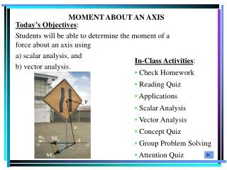
The moment of F about O is defined as. The moment vector M O is perpendicular to the plane containing O and the force F. Magnitude of M O measures the tendency of the force to cause rotation of the body about an axis along M O .

E N D
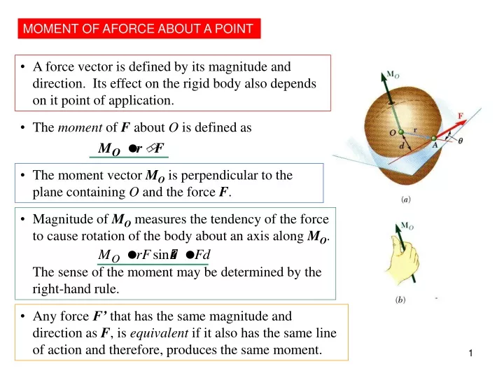
The moment of F about O is defined as • The moment vector MO is perpendicular to the plane containing O and the force F. • Magnitude of MO measures the tendency of the force to cause rotation of the body about an axis along MO. • The sense of the moment may be determined by the right-hand rule. • Any force F’ that has the same magnitude and direction as F, is equivalent if it also has the same line of action and therefore, produces the same moment. MOMENT OF AFORCE ABOUT A POINT • A force vector is defined by its magnitude and direction. Its effect on the rigid body also depends on it point of application.
Problems involving only two dimensions • Two-dimensional structures have length and breadth but negligible depth and are subjected to forces contained in the plane of the structure. • The plane of the structure contains the point O and the force F. MO, the moment of the force about O is perpendicular to the plane. • If the force tends to rotate the structure clockwise, the sense of the moment vector is out of the plane of the structure and the magnitude of the moment is positive. • If the force tends to rotate the structure counterclockwise, the sense of the moment vector is into the plane of the structure and the magnitude of the moment is negative.
3.7 VARIGNON’S THEOREM • The moment about a give point O of the resultant of several concurrent forces is equal to the sum of the moments of the various moments about the same point O. • Varigon’s Theorem makes it possible to replace the direct determination of the moment of a force F by the moments of two or more component forces of F.
Force Characteristics :Translation • No effect on equilibrium of rigid body if apply a pair of forces with equal magnitude and opposite directions along same line of action. • Only effect of couple is couple-moment.
d l F F F F M=dF O A B B F MO=lF MO=(l-d)F+dF=lF MO=(l-d)F-(l-d)F+lF=lF O A O A A couple is formed by any two parallel forces acting on the same plane with equal magnitude and opposite directions. Translation of Forces
MOMENT OF A FORCE ABOUT A POINT • The tendency of a body to rotate about an axis passing through a specific point O when acted upon by a force (sometimes called a torque).
APPLICATIONS A torque or moment of 12 N · m is required to rotate the wheel. Which one of the two grips of the wheel above will require less force to rotate the wheel?
Couple Moment • The couple-moment is known as a free vector, meaning that it can be moved anywhere in space without changing its meaning, provided that its magnitude and direction are kept intact (couple has same moment about every point in space).
135 N 135 N 100mm 135 N 100mm 100mm 100mm 90 N 135 N 150mm 90 N 3.14 Equivalent Couples Figure shows three couples which act successively on the same rectangular box. As seen in the preceding section, the only motion a couple can impart to a rigid body is a rotation. Since each of the three couples shown has the same moment M ( same direction and same magnitude M = 135 N. m ), we can expect the three couples to have the same effect on the box.
Magnitude of a moment Mo = F d N.m Mo = Magnitude of the moment of F around point O d = Perpendicular distance from O to the line of action of F MOMENT OF A FORCE ABOUT A POINT
DIRECTION OF MOMENT OF A FORCE • Moment produces a rotation. • Direction determined by using the Right-Hand Rule. • The thumb points along the moment axis and the other fingers are curled following the sense of rotation. • Could be ‘clockwise’ (CW) or ‘anti/counter clockwise’ (CCW).
Direction of Moment Choose the convenient sense of rotation for each analysis.
Calculating moment Scalar Analysis Mo= F d Mo = F (r sin θ)
Sample problem 3.1 • A 450N vertical force is applied to the end of a lever • which is attached to a shaft at O. • Determine • the moment of the 450N force about O • (b) the horizontal force applied at A which creates the • same moment about O • (c) the smallest force applied at A which creates the • same moment about O • (d) how far from the shaft a 1100N vertical force must act • to create the same moment about O • (e) whether any one of the forces obtained in parts b,c and • d is equivalent to the original force.
Solution • Moment about O • The perpendicular distance from O to the line • of action of the 450N force is d = (0.6m) cos 60˚ = 0.3 m The magnitude of the moment about O of the 450N force is Mo = Fd = (450 N) (0.3m) = 135 N.m Since the force tends to rotate the lever clockwise about O, the moment will be represented by a vector Mo perpendicular to the plane of the figure and pointing into the paper.We express this fact by writing. Mo = 135 N.m
Solution b. Horizontal Force In this case, we have d = (0.6m) sin 60˚ = 0.52 m Since the moment about O must be 135N.m, we write Mo = Fd 135 N.m = F (0.52 m) F = 260 N F= 260 N
F= 225 N 30˚ Solution c. Smallest Force Since Mo = Fd, the smallest value of F occurs when d is maximum. We choose the force perpendicular to OA and note that d = 0.6m, thus Mo = Fd 135 N.m = F (0.6 m) F = 225 N
OB cos 60˚ = d d OB = cos 60˚ Solution d. 1100 N Vertical Force In this case Mo = Fd yields 135 N.m = (1100 N)d d = 0.12 m OB = 0.24 m e. None of the forces considered in parts b,c and d is equivalent to the original 450N force. Although they have the same moment about O, they have different x and y components. In other words, although each forces tends to rotate the shaft in the same manner, each causes the lever to pull on the shaft in a different way.
Sample problem 3.2A force of 800 N acts on as bracket as shown. Determine the moment of a force about B.
Fy = 800 sin 60 A Fx= 800 cos 60 0.16 B 0.2 Solution MB = xFy + yFx = 0.2 (800 sin 60) + 0.16 (800 cos 60) = 138.564 + 64 = 202.6 Nm
135N Sample problems 3.3 A 135N force acts on the end of the 0.9 m lever as shown. Determine the moment of the force about O
135N Q = (135N) sin 20˚ = 46.2 N Mo = -Q (0.9m) = -(46.2N)(0.9m) = -41.6N.m Since the value obtained for the scalar Mo is negative, the moment Mo points into the paper. We write Mo = 41.6 N.m Solution The force is replaced by two components, one component P in the direction of OA and one component Q perpendicular to OA. Since O is on the line of action of P, the moment of P about O is zero and the moment of the 135N force reduces to the moment of Q, which is clockwise and, thus, is represented by a negative scalar.
EXAMPLE 1 Given: A 400 N force is applied to the frame and = 20°. Find: The moment of the force at A. 1) Resolve the force along x and y axes. 2) Determine MA using scalar analysis.
Solution + Fy = -400 sin 20° N + Fx = -400 cos 20° N + MA = {(400 cos 20°)(2) + (400 sin 20°)(3)} N·m = 1160 N·m
Solution: + Fy = - 40 cos 20° N + Fx = - 40 sin 20° N + MO = {-(40 cos 20°)(200) + (40 sin 20°)(30)}N·mm = -7107 N·mm = - 7.11 N·m Example 3 Given: A 40 N force is applied to the wrench. Find: The moment of the force at O. Plan: 1) Resolve the force along x and y axes. 2) Determine MO using scalar analysis.
Problems 3.1 A 90-N Force is applied to the control rod AB as shown. Knowing that the length of the rod is 225mm, determine the moment of the force about point B by resolving the force into components along AB and in a direction perpendicular to AB.
Problems 3.2 A 90-N Force is applied to the control rod AB as shown. Knowing that the length of the rod is 225mm, determine the moment of the force about point B by resolving the force into horizontal and vertical components.
3.4 m 4.8 m Solution 3.3 A 3N force P is applied to the lever which controls the auger of a snow blower. Determine the moment of P about A when αis equal to 30º.
3.4 m 4.8 m Solution
MOVING A FORCE ITS LINE OF ACTION ON Equivalent System Sliding VECTOR
Free VECTOR MOVING A FORCEOFITS LINE OF ACTION OFF
3.20 Further Reduction of a Force and Couple System If R and MRP are perpendicular to each other, the force-couple system at P can be further reduced to a single resultant force. Will be the case for system consisting either : (a) concurrent force (b) coplanar force (c) parallel forces (a) concurrent force
(b) Coplanar force systems (c) Parallel force systems
the moment of all the forces about the grip The moment of the resultant force about the grip FRd = F1d1 + F2d2 + F3d3
Sample problems 3.8 150N 600N 250N 100N • A 4.80m long beam is subjected to the forces shown. • Reduce the given system of forces to • an equivalent force couple system at A • b) single force or resultant
solution use FRd = F1d1 + F2d2 + F3d3 ;
solution 150N 250N 100N 600N F3 F2 F1 + FR =150 - 600 + 100 - 250 = - 600 N = 600 N + SMA = F1d1+ F2d2+ F3d3 =- 600(1.6m) + 100(2.8m) – 250(4.8) =- 1880 Nm
FR = 600 [N] B A d solution FRd= SMA (600) d = 1880 Nm d = 1880/600 = 3.13 m Thus, the single force equivalent to the given system; FR = 600 [N] , d = 3.13 [m]
Example • Three stage lights are mounted on a pipe as shown. The lights at A and B each weigh 16.4 N, while the one at C weighs 14 N. • If d = 0.625 m, determine the distance from D to the line of action of the resultant of the weights of the three lights. • Determine the value of d so that the resultant of the weights passes through the midpoint of the pipe.
Solution 0.25 m 0.85 m d 14 N 16.4 N 16.4 N L R = A B C D D 2.1 m For equivalence, F : - 16.4 – 16.4 – 14 = - R R = 46.8 N : - (0.25)(16.4) – (1.10)(16.4) – (1.10 + d)(14) = - L (46.8) 37.54 + 14d = 46.8 L »Eq 1
Example 3 (cont) • For d = 0.625 m, substitute the value of d in Eq 1, • 37.54 + 14 (0.625) = 46.8 L • L = 0.9891 m • The resultant passes through a point 0.9891 m to the right of D • (b) For L = 1.05 m, substitute the value of L in Eq. 1, • 37.54 + 14d = 46.8 (1.05) • d = 0.8275 m