Download
1 / 56
560 likes | 570 Views
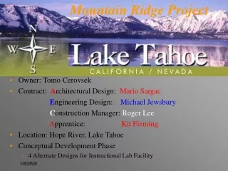
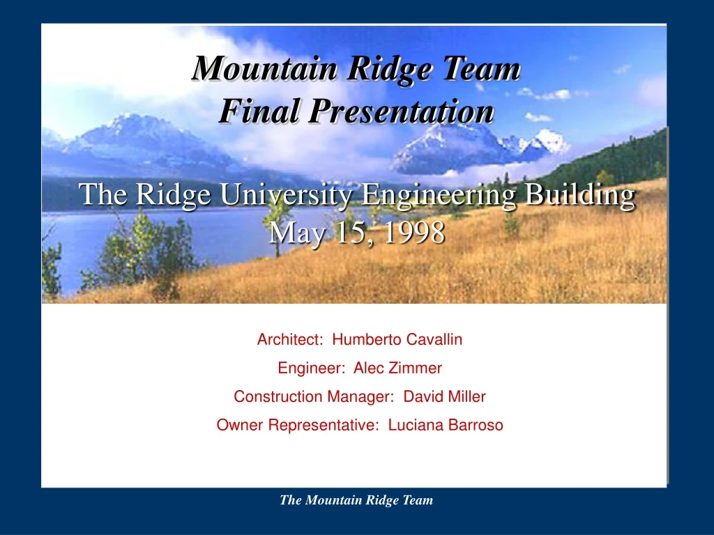
Mountain Ridge Team Final Presentation The Ridge University Engineering Building May 15, 1998. Architect: Humberto Cavallin Engineer: Alec Zimmer Construction Manager: David Miller Owner Representative: Luciana Barroso. Presentation Outline. The Project Statement

E N D
Mountain Ridge Team Final PresentationThe Ridge University Engineering BuildingMay 15, 1998 Architect: Humberto Cavallin Engineer: Alec Zimmer Construction Manager: David Miller Owner Representative: Luciana Barroso The Mountain Ridge Team
Presentation Outline • The Project Statement • Early Proposed Concepts • The Idea: Product, Evolution, and Process • The Final Product • Summary: The Team Process The Mountain Ridge Team
Project Definition • Facility: A new 30,000sf academic building for The Ridge University School of Engineering with classrooms, labs, offices and auditorium • Year: 2010 • Location: Tahoe City, California The Mountain Ridge Team
Project Definition:Physical Constraints • Must use one of 2 existing footprints The Mountain Ridge Team
Project Definition:Physical Constraints • Must use one of 2 existing footprints • 35’ height restriction • Very heavy snow loads • Moderate to high seismicity (Zone 3) • Remote site with limited access The Mountain Ridge Team
Proposed Concept - Lshape1 The Mountain Ridge Team
Proposed Concept - Square1 The Mountain Ridge Team
Proposed Concept - Lshape2 The Mountain Ridge Team
Proposed Concept -Square2 The Mountain Ridge Team
Proposed Concept -Square2 The Mountain Ridge Team
The Iterative Process Square2 E C Lshape2 A O Square1 Lshape1 First Quarter Second Quarter The Mountain Ridge Team
Site Plan The Mountain Ridge Team
The Building 1 2 3 The Mountain Ridge Team
Activities • Administrative • Students • Educational The Mountain Ridge Team
Architectural Evaluations - Floor 1 The Mountain Ridge Team
Architectural Evaluations - Floor 2 The Mountain Ridge Team
Architectural Evaluations - Floor 3 The Mountain Ridge Team
Architectural Evaluations - Section The Mountain Ridge Team
Architectural Evaluations - Section The Mountain Ridge Team
Engineering Loads-Gravity Loads Dead Loads Including 25 psf floor & partitions 10 psf MEP equipment 83.5 psf for 6.5” slab and metal deck 109.6 psf total (205 psf is seismically effective) Live Loads Including 100 psf in halls & library 50 psf in offices 40 psf in classrooms The Mountain Ridge Team
Engineering Loads-Seismic and Snow Loads Snow Loads 223 psf Ground Snow 1.0 Importance Factor 0.6 Exposure D Factor Nominally Flat Roof 133 psf roof snow load (75% is seismically effective) Seismic Loads from 1994 UBC Z = 0.3 Seismic Zone 3 T = 0.203 by Method A C = 2.75 for firm soil Rw = 8 compromise for this dual system Vbase = 608 kip Mot = 9426 k-ft The Mountain Ridge Team
Engineering Evaluations - Floor Details and Load Path Composite steel deck - concrete slab Shallow beam sections Typical Sections: Beams sizes from W10x12 to W12x30, unshored construction All columns W12x40 to facilitate connections Shear connections only Cross Beam: W10x19, Typ. Ext. Girder: W10x22, Typ. Typ. Vertical Gravity Load Transfer Column: W12x40, Typ. 12” Shearwalls Resist All Lateral Loads Second Floor Beams - Plan View The Mountain Ridge Team
Engineering Evaluations -ETABS model Verify period with modal analysis Evaluate deflections and interstory drift Verify load path assumptions Problems in model The Mountain Ridge Team
Engineering Evaluations - Cross Sections at Lines 1 and 3 • Note typical sections and detail references The Mountain Ridge Team
Third Floor Moment Frame Connection Detail Engineering Evaluations - Critical Connection Details The Mountain Ridge Team
Engineering Evaluations -Shear Wall-Beam Connection Details The Mountain Ridge Team
Engineering Evaluations -Shear Wall Design Resist all lateral loads, both seismic and wind • Mot = 1061.9 k-ft per wall • Vbase = 484 k • No boundary zones • No additional moment reinforcement • Torsional effects are negligible The Mountain Ridge Team
Engineering Evaluations - MEP Assumptions Steam heat and chilled water from central facility 15’ x15’ room provided on ground floor for equipment Circular ducts standard throughout with rectangular ducts in congested areas, 18” max. Small equipment rooms provided on all floors for advanced communications equipment Air requirements in auditorium are 20 CF/person/minute, given an approximate capacity of 250 people The Mountain Ridge Team
Engineering Evaluations - Three-Dimensional Model The Mountain Ridge Team
Contractor - Site Plan The Mountain Ridge Team
Contractor - Fall 2011Schedule The Mountain Ridge Team
Contractor - Spring 2012 Schedule The Mountain Ridge Team
Contractor - Winter Respite Analysis • Impractical to weatherproof before winter weather hits • Either shut job down during winter or rent tent for $42,000 per month • Project can still be completed comfortably if dormant for <4 months • Respite allows for coordination and planning The Mountain Ridge Team
Contractor - Estimate Details • Location adjustment factor of 1.15 • $160/s.f. 1998 dollars ($210/s.f. 2010 dollars) • 6% Contractor fee • 10% Architecture and Engineering fee The Mountain Ridge Team
Contractor - Critical Phases of Work Heaviest lift complete The Mountain Ridge Team
Contractor - Critical Phases of Work Floors and roof complete The Mountain Ridge Team
Contractor - Equipment • Crane selection for steel erection • 50T hydraulic rough terrain crane with 65’ boom • Critical lift: 4 ton beam at 60’ radius • Gradall material handlers The Mountain Ridge Team
Contractor - Estimate Progression The Mountain Ridge Team
Contractor - Schedule Loading 2011 2012 The Mountain Ridge Team
Contractor - Budget Breakdown The Mountain Ridge Team
Contractor - Inflation Analysis The Mountain Ridge Team
Contractor - Construction Cost Index The Mountain Ridge Team
A/E/C/O Height variance Ramp in rear of building 2 plane vs. 4 plane roof system C/E Beam spacing Floor system A/E/O Window wall Balcony in rear 3rd floor Shearwall Entrance façade column locations A/C/O Cladding Excavation costs Product, Evolution, and Process The Mountain Ridge Team
Floor and Structural Systems -E/C Trade-off Analysis • Concrete for floor decks: • Lightweight concrete? • Normal weight concrete? • Steel Framing: • Moment resistant frames - shop welded? • Eccentrically braced frames? • Simple gravity frames? The Mountain Ridge Team
Beam Spacing -E/C Trade-off Analysis • 20’ column grid • Beams can be spaced at 10’ or 20’ on center? • Larger beam spacing means fewer pieces, fewer connections and thus faster construction. • But, also requires deeper slabs • Cost basically unaffected • Long-term usability chosen over short-term construction schedule benefits The Mountain Ridge Team
Basement Layout vs. Excavation -A/E/C/O Trade-Off Analysis Building Functioning Space allocation slope floor, owner requirement Costs Activities and program requirements O/A Evaluation The Mountain Ridge Team
Ramp in Rear of Building -A/E/C/O Trade-Off Analysis • Relationship with the excavation • Development of the option • Rejection of the ramp alternative The Mountain Ridge Team
East Balcony and Column Locations -A/E Trade-Off Analysis Owner requirements for a balcony Architectural solution - cantilever Engineer’s response with additional columns - spares moment connections Added Columns Plan of East Balcony The Mountain Ridge Team
Window Wall and West Balcony -A/E/O Issues The Requirements of O/A/E The communications breakdowns The positioning of walkway supports The Mountain Ridge Team
Exterior Cladding -A/C/O Cost vs. Appearance Concerns Plaster or stone Stone more has institutional, timeless appearance Stone $1 million than plaster Stone/plaster combination chosen The Mountain Ridge Team