Download
1 / 68
680 likes | 699 Views
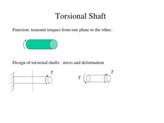
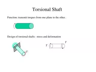
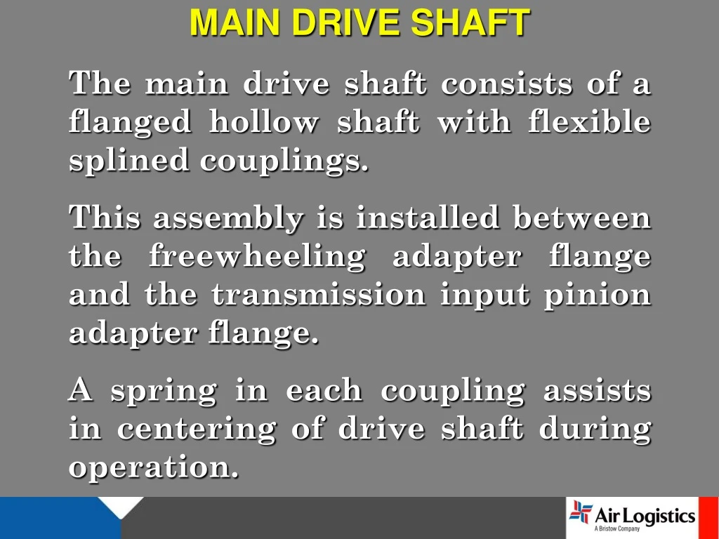
MAIN DRIVE SHAFT The main drive shaft consists of a flanged hollow shaft with flexible splined couplings. This assembly is installed between the freewheeling adapter flange and the transmission input pinion adapter flange.

E N D
MAIN DRIVE SHAFT The main drive shaft consists of a flanged hollow shaft with flexible splined couplings. This assembly is installed between the freewheeling adapter flange and the transmission input pinion adapter flange. A spring in each coupling assists in centering of drive shaft during operation.
Transmission Viewed from left side
ROTOR BRAKE The rotor brake is attached to the aft coupling of the main drive shaft and used for manually stopping drive train rotation upon shutdown. Engine starts with rotor brake engaged are prohibited. During prestart checks ensure the ROTOR BRAKE handle is Up and Latched. During the shutdown sequence the rotor brake may be applied between 38% and 30% Rotor RPM. Return the handle to the stowed position after main rotor stops.
CAUTION AVOID RAPID ENGAGEMENT OF THE ROTOR BRAKE IF HELICOPTER IS ON ICE OR OTHER SLIPPERY OR LOOSE SURFACE TO PREVENT ROTATION OF HELICOPTER. This is an optional item to the basic aircraft and information on its procedures and limitations may be found in the Supple-ments Section of the Flight Manual.
FREEWHEELING ASSEMBLY The freewheeling assembly is mounted on the engine accessory gearbox and its shaft is splined directly to the power takeoff gear shaft. Engine power is transmitted to the outer race of the freewheeling assembly, then through the full-phasing sprag elements of the assembly which couples the engine power to the transmission driveshaft.
The forward tail rotor drive short shaft connects through a flexible coupling to a splined adapter on the aft end of the freewheeling shaft that passes through the engine reduction gearbox During autorotation the main rotor drives the inner race shaft assembly. Under this condition, the freewheeling assembly provides a disconnect from the engine so the rotational forces of the main rotor are free to drive the transmission, tail rotor, and all transmission mounted accessories.
FREE WHEELING UNIT
POWERED AUTOROTATION
TAIL ROTOR DRIVE SHAFT The tail rotor driveshaft is made up of the following: forward short shaft, the oil cooler fanshaft, the aft short shaft, (5 ea.) identical, interchangeable segments connecting to the tail rotor gearbox. There are seven deep grooved ball bearings supporting these shafts, which require lubricant each 300 flight hrs. Flexible steel disc couplings connect the shaft sections. The forward short shaft and oil cooler fan shaft are made of steel, while the aft short shaft and five segments are constructed of aluminum alloy.
FWD / AFT SHORT SHAFT OIL COOLER FAN SHAFT
DRIVE SHAFT SEGMENTS TAILROTOR GEARBOX
TRANSMISSION MOUNTS NODAL BEAM The transmission, mast, main rotor hub and blade assembly are supported by and isolated from the fuselage by the transmission mounts (nodal beam) and transmission restraint. This is accomplish-ed by use of four link attachments and two stop mounts bolted to the transmission. Attached to these are four link assemblies incorporating elastomeric bearings which are secured to the four support assemblies and the flexure assemblies.
The support assemblies are bolted to the cabin roof shell and cabin roof beam and contain elastomeric bearing and bushing members to isolate and balance vibration inputs from the rotor into the flexure assemblies. The flexure assemblies are the primary vibration isolating component that provides for a vibration free ride throughout the helicopters speed range. Tuning weights are bolted to the arm and flexure assemblies and provide for the fine tuning and balance of the transmission mounting system.
The transmission restraint limits movement of the transmission through the use of an elastomeric beating and bushing member which is secured to the transmission restraint support. The support is bolted to the cabin roof shell and cabin beam along with two drag pins. The two stop mounts that are bolted to the trans-mission are installed over the drag pins. The up stops mounted on the drag pins restrict the up movement of the transmission and all oscillatory movement.
LINK ATTACHMENTS FLEXURE ASSEMBLY SUPPORT ASSEMBLIES ELASTOMERIC BEARINGS
RESTRAINT RESTRAINT SUPPORT STOP MOUNTS DRAG PINS
SUPPORT ASSEMBLIES
TRANSMISSION The main transmission is mounted forward of the engine and is coupled to the engine by means of a short drive shaft. Basically, the transmission is a reduction gearbox which transmits engine power, at reduced RPM, to the main rotor by means of a spiral bevel gear and a planetary gear stage. The transmission incorporates a self-contained lubrication system with an oil cooler.
Accessory mounting pads and drives are provided on the transmission for the hydraulic pump and rotor tachometer. The transmission is a two stage reduction of 15.23 to 1.0 (6000 RPM to 394 RPM).
TRANSMISSION MAIN CASE
TRANSMISSION UPPER CASE
OUTPUT 395 RPM (3.26 TO 1.0) PLANETARY GEAR SUN GEAR ACCESSORY DRIVE GEAR INPUT DRIVE (6016 RPM) OIL PUMP
SUMP OIL SCREEN LOWER ELECT CHIP DETECTOR XMSN OIL PUMP ROTOR TACH UPPER ELECT CHIP DETECTOR HYDRAULIC PUMP
BEGINS TO CLOSE 66˚ C, SOME OIL TO COOLER MOST BYPASSES • FULLY CLOSED 81˚ C, ALL OIL THRU COOLER, XMSN OIL SYSTEM
OPEN UNTIL 66˚C • CLOSED 81˚C
If not seated properly plug will block inlet to trans oil pump Actually BH206B pictured
SWASHPLATE AND SUPPORT ASSEMBLY The swashplate and support assembly encircles the mast directly above the trans-mission and is mounted on a universal support (pivot sleeve) which permits it to be tilted in any direction. Movement of the cyclic control stick results in a corresponding tilt of the swashplate and the main rotor. Movement of the collective pitch lever actuates the sleeve assembly which raises or lowers the swashplate and transmits collective control to the main rotor. The cyclic controls are properly coordinated with collective control by action of the mixing lever at the base of the control column.
MAST IDLER LEVER COLLAR SET BOOT IDLER LINK OUTER RING INNER RING COLLECTIVE LEVER SPHERICAL BEARING SUPPORT
MAIN ROTOR HUB AND BLADE ASSEMBLY The main rotor assembly is a two bladed, semi-rigid, see-saw type rotor with underslung mounting. The blades are mounted in the hub assembly grips with through bolts, which have hollow shanks for installation of weights to balance the hub. After balancing, the bolts must be kept with their respective rotor hub grips. Blade alignment is accomplished by adjust-ment of blade latches, which engage the root end of the blade.
The blade grips are retained on the hub yoke by means of tension-torsion strap assemblies. Changes in blade pitch angle are made by rotating the grips on the yoke journals; each grip has two pitch change bearings. The rotor blades are all metal, five piece assemblies consisting of an extruded aluminum alloy nose block, aluminum alloy trailing edge, and an aluminum honeycomb filler. A flap restraint mechanism is installed on the main rotor hub. The flap restraint assembly serves to prevent excessive flapping of the main rotor during starting and shutdown.
RETENTION NUT BLADE BOLT FLAP RESTRAINT TRUNION BEARING BLADE GRIP PITCH HORN PILLOW BLOCK YOKE PITCH CHANGE CONTROL ROD SPLIT CONES LATCH BOLT