Download

1 / 63
630 likes | 741 Views
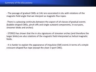
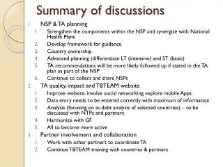
ALICE Front-end and Readout Electronics Setup & Configuration (Part 2) DCS Workshop, 10 March 2003 Peter Chochula. This talk gives a summary of discussions held since the last DCS workshop

E N D
ALICE Front-end and Readout ElectronicsSetup & Configuration (Part 2)DCSWorkshop, 10 March 2003Peter Chochula
This talk gives a summary of discussions held since the last DCS workshop • The aim of this talk is to summarize recent developments and ask questions which need to be answered by detector representatives Peter Chochula ALICE DCS Workshop, 10 March 2003
Present structure of the online systems in Alice Peter Chochula ALICE DCS Workshop, 10 March 2003
ALICE online software hierarchy ECS DCS DAQ/RC TRG HLT … SPD TPC … SPD TPC … SPD TPC LV LV HV HV FERO FERO (Source: S. Vascotto, TB presentation, October 2002) Gas Peter Chochula ALICE DCS Workshop, 10 March 2003
Partitioning of ALICE Online systems ECA PCA PCA DCS DAQ/RC TRG DCS DAQ/RC TRG Partition A Partition A (Source: S. Vascotto, TB presentation, October 2002) Peter Chochula ALICE DCS Workshop, 10 March 2003
Standard Model of Alice FERO Setup & Configuration • Systems read the configuration from DB • DAQ/RC configures FERO via DDL • DCS is involved in monitoring Config DAQ/RC DCS Config+Data Monitoring + Control JTAG, Profibus, Ethernet, etc. DDL Logging FERO Peter Chochula ALICE DCS Workshop, 10 March 2003
Synchronization of online systems • FERO can be configured only if the related detector parts are ON and well under control • DCS should be informed about the present configuration (monitoring limits etc.) • DCS can ask for reconfiguration after recovery from failure – other systems must be notified • For some architectures DCS and DAQ/RC are sharing access path to FERO Peter Chochula ALICE DCS Workshop, 10 March 2003
Alice FERO Architectures Peter Chochula ALICE DCS Workshop, 10 March 2003
Summary: Alice FERO Architectures • There are 2 options to configure FERO: • DDL based ( same as Class A) • Non-DDL (Ethernet, etc.) • DDL is used to configure FERO • Monitoring is based on different • technology DDL Configuration DDL Configuration Configuration Monitoring Monitoring FERO FERO Class A Class B • DDL is not involved in configuration • Configuration and monitoring are sharing the access path to FERO Configuration Monitoring Configuration Monitoring FERO FERO Class C Class D Peter Chochula ALICE DCS Workshop, 10 March 2003
Question 1: • To which class belongs your detector? We collected information from URDs, TDRs and from private communication with detector developers. Please help us to verify that our above presented conclusion is correct. Peter Chochula ALICE DCS Workshop, 10 March 2003
Example: The Design of HMPID PLC DCS (OPC) DCS (OPC) DCS (OPC) RO 1-3 Temp. LV (6) FEE Segments DDL 0 RO 1-3 (6) HV Segments DDL 1 Peter Chochula ALICE DCS Workshop, 10 March 2003
Example: The Design of TPC Peter Chochula ALICE DCS Workshop, 10 March 2003
Example: The Design of SPD Pilot MCM Readout Chip Sensor Bus Peter Chochula ALICE DCS Workshop, 10 March 2003
Concept of the Front-end Device (FED) Additional monitoring path PCA DCS DAQ/RC FED DDL Sw DIM Client DIM Client DDL Sw DIM Server DAQ Workstation (LDC) FED CPU LVPS PLC Profibus, JTAG, etc. DDL FERO Hardware Peter Chochula ALICE DCS Workshop, 10 March 2003
Question 2: • What is the architecture of your FED ? • ( Which hardware technology does your detector use to access the FERO?) Peter Chochula ALICE DCS Workshop, 10 March 2003
Controls Hierarchy Example: DCS is in charge of configuration PCA Commands DAQ/RC DCS Trigger Configuration CU Monitoring CU Trigger status CU Configuration DU Monitoring DU Trigger status DU FERO Hardware Status FED see C. Gaspar: Hierarchical Controls Configuration & Operation, published as a CERN JCOP framework document http://clara.home.cern.ch/clara/fw/FSMConfig.pdf Peter Chochula ALICE DCS Workshop, 10 March 2003
Controls Hierarchy Example: DAQ/RC is in charge of configuration PCA Commands Trigger DAQ/RC DCS Configuration CU Monitoring CU Trigger status CU Configuration DU Monitoring DU Trigger status DU FERO Hardware Status FED see C. Gaspar: Hierarchical Controls Configuration & Operation, published as a CERN JCOP framework document http://clara.home.cern.ch/clara/fw/FSMConfig.pdf Peter Chochula ALICE DCS Workshop, 10 March 2003
Question 3: • Which parameters you need to set/monitor? • DCS related parameters • Published services (used by other online systems) Peter Chochula ALICE DCS Workshop, 10 March 2003
FERO Configuration and Synchronization via PCA. (Classes A,B,C,D using DIM) DAQ/RC DCS DAQ/RC DCS PCA PCA FERO WS FERO WS FERO FERO PCA PCA Peter Chochula ALICE DCS Workshop, 10 March 2003
Example: Configuration of a device belonging to “CLASS A” PCA 1 Trigger DAQ/RC DCS 2 FERO CPU LVPS FERO Hardware PLC 3 DAQ/RC PCA Trigger 4 DCS Peter Chochula ALICE DCS Workshop, 10 March 2003
Example: Configuration of a device belonging to “CLASS B, C or D” PCA 1 DCS Trigger DAQ/RC 2 FERO CPU FERO Hardware DCS 3 PCA Trigger DAQ/RC 3 Peter Chochula ALICE DCS Workshop, 10 March 2003
SIU RCU Functional Overview Configuration Interface Module Data Assembler Module 32 bit FEE1 ALTRO Interface Module RO Sequencer FEE2 RCU Master Module L1 ALTRO Front End Bus Front-End Control Network Interface Module L2 Interrupts RCU bus Trigger Interface Module DCS Interface Module
DCS Interface Module • The DCS Interface module sends and receives data from the DCS • Messages are loaded from and stored to memory in the DCS I.M. 16 DCS Interface Address 32 Profibus or Ethernet Data Reset Enable R/W Safety Message Monitoring Message
TPC-FEE ECS/DCS architecture ECS/DCS mockup High Level API DIM client ? control and data flow data flow TCP/IP Ethernet DDL DIM server DCS Interface module DDL configuration interface module RCU master
ECS/DCS TPC-FEE ECS/DCS architecture PVSS DIM client DIM server Data Base Aplication Layer High Level API DIM client ? control and data flow TCP/IP Ethernet data flow DDL DIM server DCS Interface module DDL configuration interface module RCU master
Two branches of 1 Gb/s folding out to 2 * 108 RCU connections @ 100Mb/s We can transfer @ 100 Mb/s to level C Level C is done sequentially – One RCU at the time Minimum configuration time assuming 32 Mb/RCU = (12* 32 Mb)/100 Mb/s = 3.9 s A PCI NIC Ethernet DCS Architecture 1 Gb/s Ethernet 1 Gb/s Switch B 9 lines of 100 Mb/s Ethernet 100 Mb/s Switch C 12 lines of 100 Mb/s Ethernet RCU D 9 * 12 Lines = 108 RCUs
Two branches of 1 Gb/s folding out to 2 * 108 RCU connections using Ethernet-to-Profibus gateways We can transfer @ 100 Mb/s to level C Level D is done sequentially in a daisy-chain @ 12Mb/s Minimum configuration time assuming 32 Mb/RCU = (6* 32 Mb)/12 Mb/s = 16 s A PCI NIC Profibus/Ethernet DCS Architecture 1 Gb/s Ethernet 1 Gb/s Switch B 18 lines of 100 Mb/s Ethernet EthernetProfibusGateway C 6 RCUs daisy-chained @ 12Mb/s RCU RCU RCU RCU RCU RCU D
16 PCI-Profibus interfaces, 2 channels per card We can transfer @ 1.2 Mb/s to level B 6 or 7 RCUs are configured sequentially in a daisy-chain Minimum configuration time assuming 32 Mb/RCU = (7* 32 Mb)/1.2 Mb/s = 186 s Profibus DCS Architecture PCI Profibus interfaces A 32 Profibus lines 6(7) RCUs daisy-chained @ 1.2 Mb/s RCU RCU RCU RCU RCU RCU B
SPD Readout Layout Router(s) DCS PCI-MXI DAQ MXI-VME MXI-2 1 router services 6 halfstaves SPD contains 20 routers Peter Chochula ALICE DCS Workshop, 10 March 2003
SPD – FED Interface to DCS DCS / PVSS DAQ DIM Client DDL Standard Interface Private Software SPD FED SPD DATA Dedicated CPU (Workstation) DIM Server Data JTAG Return J T A G VR Control, VR Status, I,V,Temp, Time Critical tasks Halfstave control Router Peter Chochula ALICE DCS Workshop, 10 March 2003
Several agents will control the detector Control Agents (CA) will execute tasks requested by Online systems (configuration, SEU test etc.) Monitoring Agents (MA) will control selected parameters SPD Approach DIM Client Commands Data, flags Database DIM Server CA1 CA2 MA1 MA1 VISA PCI-MXI-VME Router JTAG (over private optics) + private protocol Hardware Peter Chochula ALICE DCS Workshop, 10 March 2003
. . Controlling the VME Crates – MXI Daisy-Chain • only one PCI Controller needed • programming is easy – chain is transparent to SW • performance related questions Peter Chochula ALICE DCS Workshop, 10 March 2003
. . Controlling the VME Crates – 2 PCI-MXI Bridges in one PC • two PCI Controllers needed • programming still easy – (lookup table?) • performance – we could gain using parallel processes Peter Chochula ALICE DCS Workshop, 10 March 2003
. . Controlling the VME Crates – 2 PCI-MXI Bridges in one PC • two PCI Controllers and two Computers needed • programming more complicated on upper level • performance – probably the best Peter Chochula ALICE DCS Workshop, 10 March 2003
Tasks Running on the Control Workstation “Slow” PVSS DIM Interface Local Agents FAST – Time Critical tasks Can a single machine handle this load? Do we need to separate PVSS from local control WS? Do we need to separate the two sides of detector? Do we even need more computers….? Answer can be obtained from prototypes Peter Chochula ALICE DCS Workshop, 10 March 2003
Comparison between TPC/TRD and SPD Architectures • Presented architectures (SPD and TRD/TPC) are very different in terms of • Hardware technologies (JTAG , Ethernet, Profibus, DDL, Private Optical Interface) • Software technologies (VISA and JTAG protocol, DIM and private protocol) • Detector segmentation • Low-level detector operation • The FED should hide the differences and treat the detectors in the same way Peter Chochula ALICE DCS Workshop, 10 March 2003
Direct Comparison of SPD and TRD/TPC Architecture PVSS DIM client PVSS DIM Client Commands Data, flags Commands Data, flags Database Database DIM server DIM Server Aplication Layer CA1 CA2 MA1 MA1 High Level API VISA DIM client ? PCI-MXI-VME TCP/IP Ethernet DDL DIM server Router DCS Interface module DDL configuration interface module JTAG (over private optics) + private protocol RCU master SPD Halfstave MCM Peter Chochula ALICE DCS Workshop, 10 March 2003
Direct Comparison of SPD and TRD/TPC Architecture PVSS DIM client PVSS DIM Client Commands Data, flags Commands Data, flags Database Database DIM server DIM Server Different detectors can be treated as the same device! Aplication Layer CA1 CA2 MA1 MA1 High Level API VISA DIM client ? PCI-MXI-VME TCP/IP Ethernet DDL Router DIM server JTAG (over private optics) + private protocol DCS Interface module DDL configuration interface module SPD Halfstave MCM RCU master Peter Chochula ALICE DCS Workshop, 10 March 2003
Question 4: • What is the segmentation of your detector ( in terms of FERO configuration and monitoring)? Peter Chochula ALICE DCS Workshop, 10 March 2003
Question 5: • What is the amount of data to be transferred to your FERO? Peter Chochula ALICE DCS Workshop, 10 March 2003
Typical Commands sent via DIM • Configure Sector/Detector • Check for SEU • Start/Stop/Pause Agent (to protect against access conflicts) • Modify Agent parameters (polling frequency, tolerance limits etc..) Peter Chochula ALICE DCS Workshop, 10 March 2003
Typical Monitored Parameters • Temperature • I,V • Overall FERO Status • Trigger Status (depending on architectures) • System status (paused agents, watchdogs etc..) Peter Chochula ALICE DCS Workshop, 10 March 2003
High Level Commands Supported by APIBased on discussions in Worms (March 6, 2003)Slides provided by Dieter and Uli
High Level Configuration and Monitoring API Command Structure • command(target, optionlist, data, acknowledgeCallback) : result • target encodes which detector, sector, module, front-end card, channel should receive command – reflects the granularity of the detector. • - optionlist and data are command specific • - for valid command values see below. • optionlist and data can be empty • some commands support an optional acknowledgeCallback specified by the result ACK. Peter Chochula ALICE DCS Workshop, 10 March 2003
Comment by Peter This is sometimes called calibration Peter Chochula ALICE DCS Workshop, 10 March 2003
Comment by Peter This can be used for SEU monitoring Peter Chochula ALICE DCS Workshop, 10 March 2003