Download
1 / 20
200 likes | 433 Views
Asparagus Gauging System (AGS). By Ryan Moore and Gerti Tuzi Advisor: Dr. Miller. Brief Background. Asparagus is currently picked manually. Harvesting must be done hourly due to rapid growth. Slow, costly, and hard labor conditions. Automated asparagus picker proposed.

E N D
Asparagus Gauging System (AGS) By Ryan Moore and GertiTuzi Advisor: Dr. Miller
Brief Background • Asparagus is currently picked manually. • Harvesting must be done hourly due to rapid growth. • Slow, costly, and hard labor conditions. • Automated asparagus picker proposed. • Needs to independently identify ripe asparagus.
General Performance Requirements • Marketable asparagus must be 6” or more in height. • Asparagus picking machine requires real world coordinates for operation. • Must be operational in farming environment • Varying lighting conditions • Vehicle mobility • Noisy background (dust, trees, motion jitters, etc)
Project Objective • To design a computer aided vision system which detects asparagus in an open farming environment. • Must be able to locate and determine height of asparagus. • System is to be integrated in the mobile asparagus picking machine.
Physical Performance Characteristics • Single out desired asparagus using directed light. • Mark the asparagus. • Allows identification (light marker) • Light source must be more intense than background light. • Only desired object are detected • Higher light intensity would facilitate detection. • Increase signal to noise ratio. • Predetermined-angled light source. • Allows determination of real world location. • Measure asparagus height.
Physical Setup Geometrical Setup
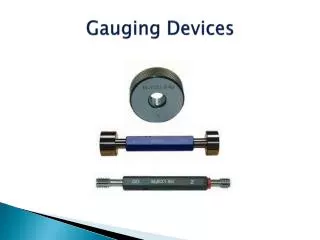
Hardware Components • IR Light Source: • High power IR LED, used to generate IR light beam. • Light beam focused through a cylindrical lens to generate a focused line. • IR Digital Camera: • IR-pass filter to capture light reflection from asparagus. • Remove most visible light
DC Infrared Light Circuit DC Circuit Setup
Digital Performance Characteristics • Digital camera captures light marker on asparagus . • Minimize background noise (light) interference. • Controlled exposure times. • Detect asparagus light marker in image. • Remove background noise. • Differentiate between background and foreground. • Identify objects in image. • Coordinate location and height gauging. • Extract digital information from each object. • Convert digital information into real world measurements.
Digital Part Overview Detect Objects Extract Coordinates Asparagus Picking Machine Digital To Physical Coordinate Conversion AGS External System
Object Detection • Steps in object detection: • Background vs. Foreground Differentiation • Morphological Transformation, Binary Thresholding, • Object Detection. • Blob Detection • Size Based Filtering • Image Digital Coordinate Determination of Positive Objects • Collect and return blob coordinates .
Detection ProcessModular View Output Information Binary Thresholding (Otsu’s Method) Physical Location Translation Filtering Morphological Open Digital Coordinate Extraction Blob Detection
Otsu’s Method Thresholding • Finds threshold based on intensity distribution. • Adjusts to account for lighting changes. • Minimizes overlapping of foreground and background. • Algorithm is fast on large images.
Morphological Filtering Overview • Perform an open operation to remove small objects • Remove desired shapes and subtract the background. Structuring Element
Blob Detection • Blobs are defined as a connected group of pixels. • Each blob object is identified by (x,y) digital coordinates, area, and width and height. • Falsely detected blobs are restricted based on area.
Real World Location World vs. Digital Image Relation World Distance Equation Marker Height Equation • Data extracted from digital images were plotted against respective world measurements. • Strong relationship between digital and world measurements
Remaining tasks • Create a strobe circuit to increase the intensity of the light. • Outdoor implementation. • Perform a test in the actual farming environment. • Optimize the morphological filter • Implement object tracking. • Add the Fresnel lens. • Simplify physical setup. • Increase range of detection.