Download
1 / 68
690 likes | 925 Views
IZM Communication Architecture. IZM Communication Architecture. Part 1: The communicative hardware system Part 2: Supplement to the communicative hardware Part 3: IZM communication via PROFIBUS DP Part 4: Further information about the additional modules

E N D
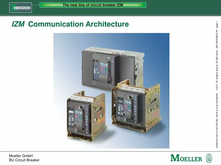
The new line of circuit breaker IZM IZM Communication Architecture
The new line of circuit breaker IZM IZM Communication Architecture Part 1: The communicative hardware system Part 2: Supplement to the communicative hardware Part 3: IZM communication via PROFIBUS DP Part 4: Further information about the additional modules Part 5: Further inf. about the measurement modules
The new line of circuit breaker IZM IZM Communication Architecture Part 1: The communicative hardware system • Communication interfaces on the IZM circuit-breaker • Modes of the IZM parameter assignment moduleIZM-XEM-PG(E) with integrated web server
Parameter assignment module with integral web server IZM-XEM-PG IZM-XEM-PGE The new line of circuit breaker IZM Overview of the IZM communication architecture Data acquisition and processing Parameterization and visualisation tool via PROFIBUS DP Output devicee.g. Notebook with Browser Circuit-breaker internal system bus Moeller IZM XCOM-DP XBSS ZSI module Digital output modulerelay Digital output moduleoptocoupler Digital output modulerelay, configurable Digital output moduleoptocoupler, configurable Analog output module Digital input module Trip unit XMP(H) Part 1: The communicative hardware system
The new line of circuit breaker IZM Structure of the internal system bus with communicative devices Part 1: The communicative hardware system
One unit for parameter setting, for operation and for visualization of Moeller circuit-breakers IZM based on “html” technology PROFIBUS software, which offers the same option via the PROFIBUS-DP(Moeller Software planed for 2004) The new line of circuit breaker IZM Communication: Local, Ethernet, Internet or PROFIBUS Parameter assignment module with integrated web server System software Part 1: The communicative hardware system
The new line of circuit breaker IZM IZM communication via PROFIBUS DP Necessary modules for communication via PROFIBUS DP: BSS Breaker Status Sensor(internal) XCOM-DP Profibus Module(external) Part 1: The communicative hardware system
Parameterization, operation, observation and diagnostics of IZM circuit breaker IZM-XEM-PG(E) provides its data in “html” format (Masks and data are transmitted together) No add. software installation is necessary(Java 2 VM is a premise, e.g. with Internet Explorer) Data representation in a tree-structure enables fast access to the requested information IZM-XEM-PGE offers an additional Ethernet gateway Remote control of the IZM circuit-breaker withlong-distance data transmission The new line of circuit breaker IZM IZM parameter assignment module IZM-XEM-PG (E)with integrated web server Part 1: The communicative hardware system
The new line of circuit breaker IZM IZM-XEM-PG in Offline Mode (no connection to an IZM trip unit) • Parameter data can be created and saved on the PC • Opening, modification and saving of parameter files which already exist • One IZM-XEM-PG for every MoellerIZM circuit breaker in the power distribution system Application examples: • Preperation of the commissioning in the office; e.g. paramerterization • No expert know-how required in the system Part 1: The communicative hardware system
The new line of circuit breaker IZM IZM-XEM-PG in Temporary Mode - Local • Communication via RS485 (IZM), RS232 (to the Notebook) • Parameterization, control and diagnostics of the IZM with its communicative modules • Parameter settings can be saved and printed as documentation • One IZM-XEM-PG for all IZM in a power distribution system Applications examples: • “On-site” parameterization and diagnostics • Fault analysis via event history Circuit-breaker internalsystem bus Moeller IZM Part 1: The communicative hardware system
Circuit-breaker internalsystem bus Moeller IZM The new line of circuit breaker IZM IZM-XEM-PGE in fixed mounted mode with Ethernet communication • IZM-XEM-PGE is permanently connected to a Moeller IZM trip unit • One IZM-XEM-PGE per circuit-breaker • Remote access to the Moeller IZM circuit-breaker via Ethernet Application example: • Communication without PROFIBUS DP • For a small number of circuit-breakers in industry or buildings • For “Offshore” applications Part 1: The communicative hardware system
The new line of circuit breaker IZM IZM Communication Architecture Part 2: Supplement to the communicative hardware • Circuit-breaker internal system bus • Overview electronic overcurrent releases • “Power” and “Harmonic” measurement functions • Intelligent, external expansion modules IZM Communication Architecture
Parameter assignment module with integral web server IZM-XEM-PG IZM-XEM-PGE The new line of circuit breaker IZM Overview of the IZM communication architecture Data acquisition and processing Parameterization and visualisation tool via PROFIBUS DP Output devicee.g. Notebook with Browser Circuit-breaker internal system bus Moeller IZM XCOM-DP ZSI module Digital output modulerelay Digital output moduleoptocoupler Digital output modulerelay, configurable Digital output moduleoptocoupler, configurable Analog output module Digital input module Trip unit Part 2: Supplement to the communicative hardware
The new line of circuit breaker IZM The way of the internal system bus Part 2: Supplement to the communicative hardware
The new line of circuit breaker IZM Cicruit-breaker internal system bus The circuit breaker internal system bus connects all intelligent modules within the IZM circuit-breaker with each other. In addition it enables the connection of external additional modules to the circuit-breaker. Intelligent, internal modules: • “U”, “R”, “D” electronic trip units • “Power“ and “Harmonic” measurement functions • BSS Breaker Status Sensor External additional modules: • XCOM-DP PROFIBUS module • Digital input + output modules • Analog output module • ZSI - module • Parameter assignment module IZM-XEM-PG (E) Part 2: Supplement to the communicative hardware
The new line of circuit breaker IZM Circuit-breaker internal system bus: System conditions Maximum assignment on the internal system bus: ModuleNumberRemark Analog output module 2 varying coding positions Digital output module with rotary coding switch 2 varying coding positions Digital output module, configurable 1 Digital input module 2 varying coding positions ZSI - module 1 Maximum length of the internal system bus: 10 m 1x 24 V DC supply voltage, termination resistor on last additional module Part 2: Supplement to the communicative hardware
The new line of circuit breaker IZM Advantages of the circuit-breaker internal system bus • integrated into the trip unit types U, R, D of the IZM without extra charge • high levels of system availability and minimum installation effort via safe and simple connection of the modules with RJ 45 jacks • fast reaction times of the entire system • retrofitting of all modules possible in a record time • considerable additional usage and potential for savings by use of the external additional modules, which enables interfacing of further peripheral devices to the IZM Part 2: Supplement to the communicative hardware
XZMD XZMR XZMV XZMU XZMV XZMA The new line of circuit breaker IZM Type overview of the electronic overcurrent releases XZMA XZMV XZMV+XT XZMU (+XT) XZMR (+XT) XZMD (+XT) L-I L-S-I L-S-I-N-G L-S-I (-N-G) L-S-I (-N-G) L-S-I (-N-G) Earth fault protection ‚XT‘ is optional and for type ‚U‘, ‚R‘ and ‚D‘ even modular for retrofitting. Part 2: Supplement to the communicative hardware
The new line of circuit breaker IZM Type overview of the electronic overcurrent releases XZMA Release for power distribution system protection XZMV Release for selective (discriminative) protection XZMU Release for universal protection XZMR Digital release, for external parameterization only XZMD Digital release Circuit breaker with trip units type ‘U’, ‘R’ and ‘D’are already equipped with the internal system bus Part 2: Supplement to the communicative hardware
The new line of circuit breaker IZM Trip units: The different protective ranges IZM trip units: LInverse time-delay overLoad rangeA, V, V+XT, U, R, D SShort-time delay short-circuit trippingV, V+XT, U, R, D IInstantaneous short-circuit trippingA, V, V+XT, U, R, D NNeutral conductor overload trippingV+XT, U, R, D GEarth fault tripping (Ground fault)V+XT, U+XT(A), R+XT(A), D+XT(A) +XT = earth-fault release additional equipment Part 2: Supplement to the communicative hardware
The new line of circuit breaker IZM “Power” and “Harmonic” Measurement Functions “Power” “Harmonic” Currents Voltages Powers Cos phi Energy values Frequency Total harmonic distortion, form factor, peak factor As with “Power”, with additional • Frequency analysis up to 29th harmonic • Recording of currents and voltages in waveform memory (two ring buffers enable graphic evaluation of current and voltage waveshape) The measurement module is installed in the IZM on the rear side of the trip unit Part 2: Supplement to the communicative hardware
The new line of circuit breaker IZM “Power” and “Harmonic” Measurement Functions Advantages of the measurement modules • High level of measurement accuracy of 1% for current and voltage • Communication interfaced via the XCOM-DP and circuit-breaker Parameter assignment module • Space-saving internal installation in the circuit-breaker • Signalling of events in the network offer extended protective functions and a higher level of power distribution system protection • Good alternative for external measurement devices (reduced installation effort and space requirement) Part 2: Supplement to the communicative hardware
The new line of circuit breaker IZM Digital input module Application possibilities • Offers connection features for max. 6 additional potential free binary signals, 24 VDC • Enables the transfer of additional binary information via the PROFIBUS DP to the field bus level e.g.: • State of the control panel door • State of the MCCB‘s • State of the switch-disconnector • Overtemperature in the control panel • State of the control panel forced ventilation Part 2: Supplement to the communicative hardware
T-2 T-3 G The new line of circuit breaker IZM Digital input module Application example: • For use in conjunction with the “R” or “D”trip unit for switchover of the parameter sets (A and B) saved in the trip unit. Simple and fast switchover between the regenerative and mains operation possible When used for parameter switchover, all further inputs of the module cannot be used Part 2: Supplement to the communicative hardware
The new line of circuit breaker IZM Variants of the digital output modules Relay outputs • Control of electromagnetic devices • Rotary coding switch • Configurable Optocoupler outputs • Transfer of commands and messages for electronic devices • Rotary coding switch • Configurable Part 2: Supplement to the communicative hardware
The new line of circuit breaker IZM Digital output module with rotary coding switch Application possibilities (1) • 6 digital outputs available for differentiated trip causes signalling, warnings, threshold value overshoots to external signalling devices (e.g. lamps, horns) • Event controlled operation (switch on / off) of non-Profibus capable power distribution lements,e.g. fans, motors, heating or pumps (which have a different supply and protection). Part 2: Supplement to the communicative hardware
The new line of circuit breaker IZM Digital output module with rotary coding switch Application possibilities (2) • Selective switch off of frequency inverters by early-make overload tripping • Integration in process automation via time-delayed control with e.g. load pick up or load shedding • Simple setting of the assignment and the time delay of the outputs via rotary coding switches Part 2: Supplement to the communicative hardware
The new line of circuit breaker IZM Digital, configurable output module Application possibilities • All functions of the module with rotary coding switch including • 6 freely configurable digital outputs available for all event messages, e.g. for • Status messages (on, off, tripped, ready-to-close) • Warnings (overload, load shedding, earth fault) • Trips (overload, short circuit, phase unbalance) • Threshold value overshoot (phase unbalance, distortion factor) • Configuration possible with IZM-XEM-PG(E) or remote controlled via PROFIBUS-DP Part 2: Supplement to the communicative hardware
The new line of circuit breaker IZM Analog output module Application possibilities • 4 analog outputs, 4-20 mA or 0-10 V available • With the IZM measured values can be easily output to external analog instruments: • Phase currents and neutral conductor current, • Phase unbalance of the current, • Active power of the individual phases and as a sum total, • Power factors of the individual phases and as average value • Frequency, etc. Part 2: Supplement to the communicative hardware
The new line of circuit breaker IZM ZSI module (Zone Selective Interlocking) • Optimized selectivity in the range between Isd and Ii • Short delay time tZSI = 50 ms with full selectivity independent of the number of group levels • ZSl locates the short-circuit • Only the next circuit-breaker in the direction of power flow will be switched off with a short-circuit and / or earth-fault • Reduces the stresses which occur and the damage in the power distribution system during a short-circuit • ZSI – module can be retrofitted with minimum effort at any time Part 2: Supplement to the communicative hardware
The new line of circuit breaker IZM IZM Communication Architecture Part 3: IZM communication via PROFIBUS DP • Modules for communication via PROFIBUS DP • The 3-step communication concept • The three basic types for cyclic data interchange • Classification of the signals to be processed IZM Communication Architecture
The new line of circuit breaker IZM IZM communication via PROFIBUS DP Necessary modules for communication via PROFIBUS DP: BSS Breaker Status Sensorinternal XCOM-DP Profibus Module(external) Part 3: IZM communication via PROFIBUS DP
The new line of circuit breaker IZM IZM communication via PROFIBUS DP BSS Breaker Status Sensor = internal microswitch scanner unit Internal circuit-breaker information: 1. Main contacts ON / OFF2. Spring charged 3. Ready-to-close 4. Tripped signal5. Temperature in circuit-breaker6. Signal switches on 1st & 2nd voltage releases Part 3: IZM communication via PROFIBUS DP
Einschaltbereitschaft Ready-to-close Hauptkontakte (EIN/AUS) Main contact (ON/OFF) Federspeicherzustand Spring charged The new line of circuit breaker IZM IZM communication via PROFIBUS DP Breaker Status Sensor BSS - who signalises what? Part 3: IZM communication via PROFIBUS DP
The new line of circuit breaker IZM IZM communication via PROFIBUS DP XCOM-DP PROFIBUS Modules Functions: • enables remote operated on/off switching, reset, etc. • setting and modification of all protection parameters, measured value settings, communication parameters, etc. • simple diagnostics by LED status display • support for DPV1 PROFIBUS expansion Part 3: IZM communication via PROFIBUS DP
The new line of circuit breaker IZM DPV1 functionality supported Communication without DPV1 (with DPV 0): • Data are transferred exclusively during cyclic data exchange process • Data quantity cannot be changed during operation • Low performance if the quantity of data is too large (e.g. 100 Bytes) IZM communication with DPV1: • Transfer of the data sets (DS) with up to 245 bytes in only one additional acyclic telegram • DPV1 telegrams are initiated by an application program, just transferred once (e.g. with the system software) • Cyclic data transfer runs in parallel Part 3: IZM communication via PROFIBUS DP
The new line of circuit breaker IZM IZM communication via PROFIBUS DP XCOM-DP PROFIBUS Module Additional signals: • time stamp: each event can be allocated to a time • micro switch on XCOM-DP - Module: position of the withdrawable circuit-breakers connected test disconnected • integrated temperature sensor: temperature in the cubicle • free assignment: 1 input, 1 output Part 3: IZM communication via PROFIBUS DP
The new line of circuit breaker IZM IZM communication via PROFIBUS DP XCOM-DP PROFIBUS Module Connections and LED‘s: LED PROFIBUS: Off: No voltage on XCOM-DPRed: Fault on Profibus or Profibus not addressableGreen: Profibus communication OK LED internal system bus: Off: No system station foundRed: Error on system busGreen: System bus station found & communication OK System bus connection (on rear side) PROFIBUS interface Part 3: IZM communication via PROFIBUS DP
The new line of circuit breaker IZM Status signals for the communication Signalling switches: (1) Spring charged S41 (2) Breaker ON/OFF S44 (3) Ready-to-close S40 (4) Tripped S45 (5) Status 1st shunt release S42 (6) Connected position S46 (7) Test position S47 (8) Disconnected position S48 (9) Status 2nd shunt release or undervoltage release S43 Part 3: IZM communication via PROFIBUS DP
The new line of circuit breaker IZM The 3-Step Communication Concept: 1) fast, easy, master class 1 2) adaption of the three basic types 3) acyclic data exchange, master class 1 or 2 Part 3: IZM communication via PROFIBUS DP
The new line of circuit breaker IZM 3 Basic types(choice out of more than 400 data points) Basic type 1 status + 4 values (à 2 byte) = 14 byte Basic type 2 status + 8 values (à 2 byte) = 26 byte Basic type 3 status + 14 values (à 2 byte) = 44 byte Part 3: IZM communication via PROFIBUS DP
The new line of circuit breaker IZM Communication with reference to the PROFIBUS User Organization Profile 1 Device Classes 1.1 Circuit-Breaker 1.2 Starters 1.3 Switches 1.4 Overload Relay 1.5 Contactor 1.6 Auxiliary Switching Devices 1.7 Control and Protective Switching Devices (or Equipment) Part 3: IZM communication via PROFIBUS DP
The new line of circuit breaker IZM Default assignment basic type 1 = Format 1 PNO Profil LVSG Part 3: IZM communication via PROFIBUS DP
The new line of circuit breaker IZM Default assignment basic type 2 = Format 2 PNO Profil LVSG Part 3: IZM communication via PROFIBUS DP
The new line of circuit breaker IZM Default assignment basic type 3 = Format 3 PNO Profil LVSG Part 3: IZM communication via PROFIBUS DP
The new line of circuit breaker IZM Binary Status Information in the Cyclic Message / 1 Part 3: IZM communication via PROFIBUS DP
The new line of circuit breaker IZM Binary Status Information in the Cyclic Message / 2 Part 3: IZM communication via PROFIBUS DP
The new line of circuit breaker IZM Control bytes to the IZM circuit-breaker / 1 Part 3: IZM communication via PROFIBUS DP
The new line of circuit breaker IZM Control bytes to the IZM circuit-breaker / 2 Part 3: IZM communication via PROFIBUS DP
The new line of circuit breaker IZM Which is the source for requested information? Part 3: IZM communication via PROFIBUS DP