Download
1 / 12
120 likes | 131 Views
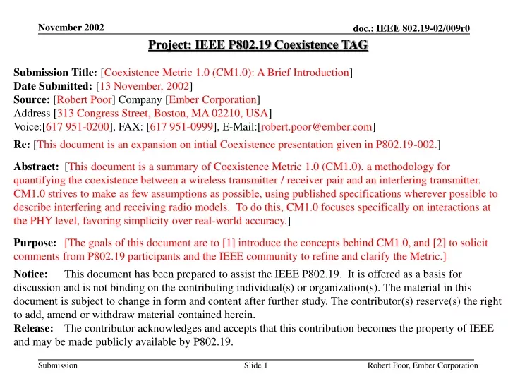
Project: IEEE P802.19 Coexistence TAG Submission Title: [ Coexistence Metric 1.0 (CM1.0): A Brief Introduction ] Date Submitted: [ 13 November, 2002 ] Source: [ Robert Poor ] Company [ Ember Corporation ] Address [ 313 Congress Street, Boston, MA 02210, USA ]

E N D
Project: IEEE P802.19 Coexistence TAG Submission Title: [Coexistence Metric 1.0 (CM1.0): A Brief Introduction] Date Submitted: [13 November, 2002] Source: [Robert Poor] Company [Ember Corporation] Address [313 Congress Street, Boston, MA 02210, USA] Voice:[617 951-0200], FAX: [617 951-0999], E-Mail:[robert.poor@ember.com] Re: [This document is an expansion on intial Coexistence presentation given in P802.19-002.] Abstract: [This document is a summary of Coexistence Metric 1.0 (CM1.0), a methodology for quantifying the coexistence between a wireless transmitter / receiver pair and an interfering transmitter. CM1.0 strives to make as few assumptions as possible, using published specifications wherever possible to describe interfering and receiving radio models. To do this, CM1.0 focuses specifically on interactions at the PHY level, favoring simplicity over real-world accuracy.] Purpose:[The goals of this document are to [1] introduce the concepts behind CM1.0, and [2] to solicit comments from P802.19 participants and the IEEE community to refine and clarify the Metric.] Notice: This document has been prepared to assist the IEEE P802.19. It is offered as a basis for discussion and is not binding on the contributing individual(s) or organization(s). The material in this document is subject to change in form and content after further study. The contributor(s) reserve(s) the right to add, amend or withdraw material contained herein. Release: The contributor acknowledges and accepts that this contribution becomes the property of IEEE and may be made publicly available by P802.19. Robert Poor, Ember Corporation
Coexistence Metric 1.0 (CM1.0)A Brief Introduction Robert Poor <robert.poor@ember.com> Jim Lansford <jim.lansford@mobilian.com> The goal of CM1.0 is to provide a simple framework that gives a quantitative answer the question “How much will this wireless interferer disrupt the operation of that wireless receiver?” Robert Poor, Ember Corporation
Design Principals for CM1.0 • Base models on quantitative specifications. • Favor a simple framework. • Produce intuitive results. • Build upon previous work. • Establish bounds: Err on the pessimistic side. • Use a portable, widely supported framework. • Create an open process: Publish early, revise often. Robert Poor, Ember Corporation
CM1.0: The Model • FER is expressed as a function of the distance separating interferer and receiver. Robert Poor, Ember Corporation
CM1.0 Assumptions • A single transmitter is the sole source of signal. • A single interferer is the sole source of noise. • Interfering energy appears as Additive White Gaussian Noise (AWGN) at the receiver. • Filters and center frequencies are assumed to be perfectly matched. Robert Poor, Ember Corporation
Path Loss Model • Adopted from TG2/Marquess, suitable model for 2.4GHz indoor systems. • Path loss exponent = 2 for first 8 meters, = 3.3 thereafter Robert Poor, Ember Corporation
Area AI Area AF Spectral Coupling • “How much of interferer’s energy gets past the receiver’s input filter?” • Based on published specifications. • Af / Ai, expressed as attenuation in dB. Robert Poor, Ember Corporation
CM1.0 Parameter Set A radio is characterized by 9 simple attributes: • public String description(); • public boolean isFrequencyHopped(); • public Channel[] getChannels(); • public double receiveSensitivity(); • public Spectrum receiveSpectrum(); • public double bitErrorRate(double sirDB); • public int bitsPerPacket(); • public double transmitPower(); • public Spectrum transmitSpectrum(); Robert Poor, Ember Corporation
A typical driver file public class T15d3_15d4 { public static void main(String args[]) { // Create an array of distances ranging from .1M to 100M double dist[] = Util.makeDistances(); // Allocate an 802.15.3 object to be used as the receiver RM802_15_3 recvr = new RM802_15_3(RM802_15_3.MBPS_22); // Allocate an 802.15.4 object to be used as the interferer RM802_15_4 intfr = new RM802_15_4(); // Compute bit error rate as a function of distance double ber[] = Coexistence.coexistence(recvr, intfr, dist); // Convert bit error rate into packet error rate double per[] = Coexistence.packetErrorRate(recvr, ber); // Print a descriptive header double offset = recvr.getFrequencySeparation(intfr)/1.0e6; System.out.println("Packet Error Rate vs Separation"+ ", Receiver="+recvr.description()+ ", Interferer="+intfr.description()+ ", offset="+offset+"MHz"); // Print column header System.out.println("separation(M)\tBER\tPER"); // Print separation in meters, bit error rate, packet error rate for (int i=0; i<dist.length; i++) { System.out.println(Util.formatScientific(dist[i])+ "\t"+Util.formatScientific(ber[i])+ "\t"+Util.formatScientific(per[i])); } } } Robert Poor, Ember Corporation
Packet Error Rate vs Separation, Receiver=802.15.3(22Mbps), Interferer=802.15.4, offset=7.0MHz separation(M) BER PER 1.000E-01 4.972E-01 1.000E00 1.072E-01 4.970E-01 1.000E00 1.148E-01 4.968E-01 1.000E00 1.230E-01 4.966E-01 1.000E00 … 1.905E01 1.050E-02 1.000E00 2.042E01 4.850E-03 1.000E00 2.188E01 1.900E-03 1.000E00 2.344E01 6.314E-04 9.943E-01 2.512E01 1.461E-04 6.979E-01 2.692E01 2.393E-05 1.780E-01 2.884E01 2.540E-06 2.060E-02 3.090E01 1.563E-07 1.280E-03 3.311E01 4.851E-09 3.974E-05 3.548E01 6.370E-11 5.218E-07 3.802E01 2.840E-13 2.326E-09 4.074E01 3.261E-16 2.728E-12 4.365E01 6.813E-20 1.000E-100 4.677E01 1.674E-24 1.000E-100 5.012E01 2.797E-30 1.000E-100 5.370E01 1.597E-37 1.000E-100 5.754E01 1.312E-46 1.000E-100 6.166E01 5.237E-58 1.000E-100 6.607E01 2.597E-72 1.000E-100 7.079E01 2.885E-90 1.000E-100 7.586E01 1.000E-100 1.000E-100 8.128E01 1.000E-100 1.000E-100 8.710E01 1.000E-100 1.000E-100 9.333E01 1.000E-100 1.000E-100 Typical Results Robert Poor, Ember Corporation
Frequency Hopped Receiver Robert Poor, Ember Corporation
Status and Next Steps • CM1.0 has been coded in Java and was used for TG4 coexistence annex. • Need to find a suitable repository for CM1.0 source code & a mechanism for updates. • Compare measured results against CM1.0 predictions. • Consider PHYs outside 2.4GHz range, notably 5GHz and UWB. Robert Poor, Ember Corporation

![Project: IEEE Coexistence Study Group Submission Title: [Coexistence Among the PHYs]](https://cdn3.slideserve.com/5598451/slide1-dt.jpg)
![Project: IEEE P802.19 Coexistence TAG Submission Title: [SG3a Coexistence Criteria Proposal]](https://cdn3.slideserve.com/6311489/slide1-dt.jpg)

![Project: IEEE P802.19 Coexistence TAG Submission Title: [ Common Signaling for UWBCoexistence ]](https://cdn5.slideserve.com/9402577/project-ieee-p802-19-coexistence-tag-submission-dt.jpg)