Download
1 / 1
10 likes | 96 Views
1. 5. 2. 3. 4. 5. 4. 3. 1. 2. Increase E-field strength. Photonic band gap tuning in chiral nematic LCs S. S. Choi 1 , S.M. Morris 1 , W.T.S. Huck 2 , H.J. Coles 1

E N D
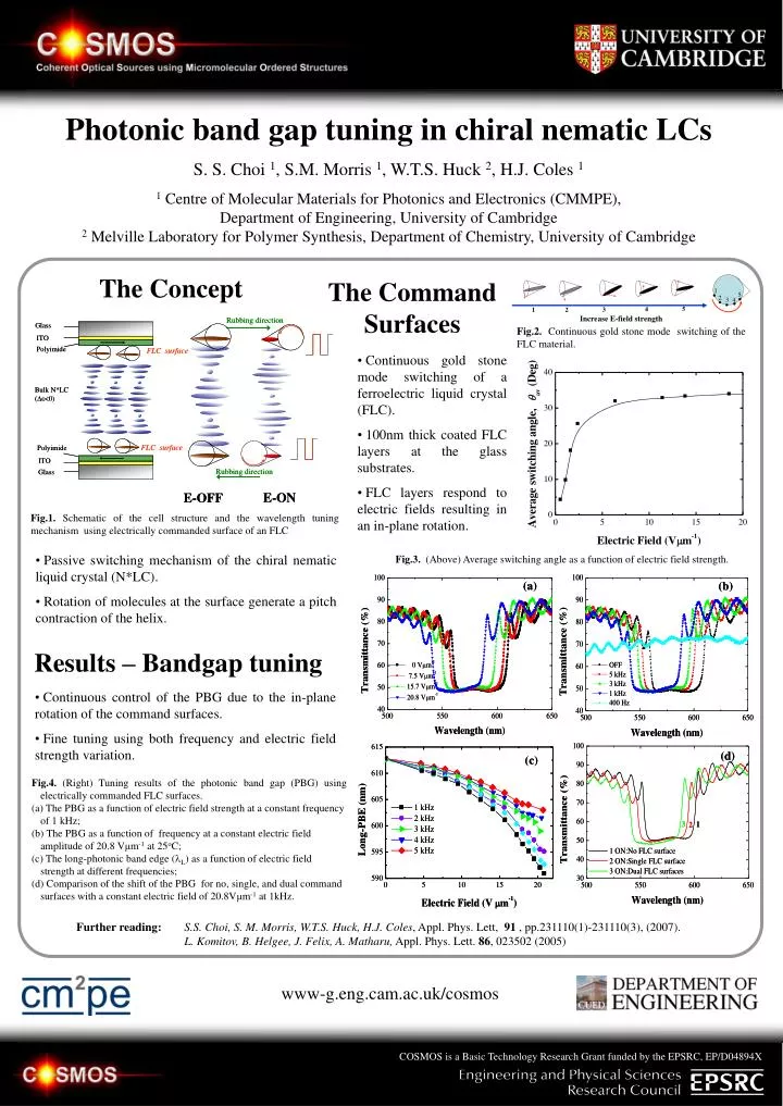
1 5 2 3 4 5 4 3 1 2 Increase E-field strength Photonic band gap tuning in chiral nematic LCs S. S. Choi 1, S.M. Morris 1, W.T.S. Huck 2, H.J. Coles 1 1Centre of Molecular Materials for Photonics and Electronics (CMMPE),Department of Engineering, University of Cambridge2 Melville Laboratory for Polymer Synthesis, Department of Chemistry, University of Cambridge The Concept The Command Surfaces Fig.2. Continuous gold stone mode switching of the FLC material. • Continuous gold stone mode switching of a ferroelectric liquid crystal (FLC). • 100nm thick coated FLC layers at the glass substrates. • FLC layers respond to electric fields resulting in an in-plane rotation. Fig.1. Schematic of the cell structure and the wavelength tuning mechanism using electrically commanded surface of an FLC • Passive switching mechanism of the chiral nematic liquid crystal (N*LC). • Rotation of molecules at the surface generate a pitch contraction of the helix. Fig.3. (Above) Average switching angle as a function of electric field strength. Results – Bandgap tuning • Continuous control of the PBG due to the in-plane rotation of the command surfaces. • Fine tuning using both frequency and electric field strength variation. • Fig.4. (Right) Tuning results of the photonic band gap (PBG) using electrically commanded FLC surfaces. • The PBG as a function of electric field strength at a constant frequency of 1 kHz; • (b) The PBG as a function of frequency at a constant electric field amplitude of 20.8 Vμm-1 at 25oC; • (c) The long-photonic band edge (L) as a function of electric field strength at different frequencies; • (d) Comparison of the shift of the PBG for no, single, and dual command surfaces with a constant electric field of 20.8Vμm-1 at 1kHz. Further reading:S.S. Choi, S. M. Morris, W.T.S. Huck, H.J. Coles, Appl. Phys. Lett, 91, pp.231110(1)-231110(3), (2007). L. Komitov, B. Helgee, J. Felix, A. Matharu, Appl. Phys. Lett. 86, 023502 (2005) www-g.eng.cam.ac.uk/cosmos COSMOS is a Basic Technology Research Grant funded by the EPSRC, EP/D04894X