Download
1 / 27
280 likes | 460 Views
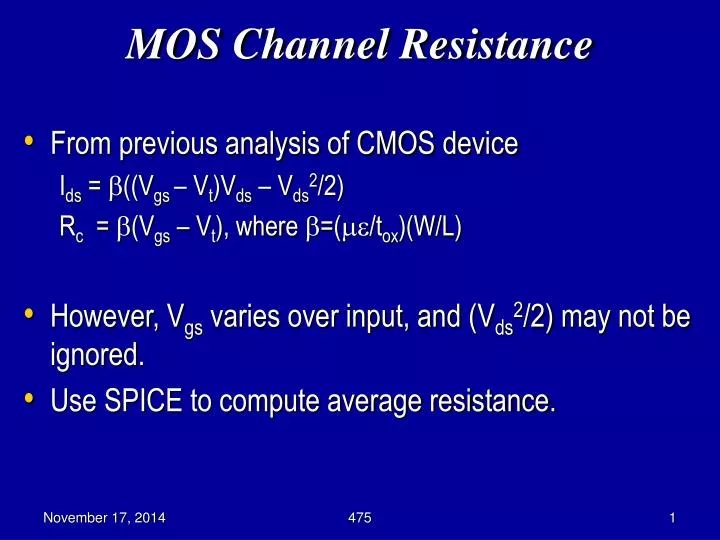
MOS Channel Resistance. From previous analysis of CMOS device I ds = ((V gs – V t )V ds – V ds 2 /2) R c = (V gs – V t ), where =(/t ox )(W/L) However, V gs varies over input, and ( V ds 2 /2) may not be ignored. Use SPICE to compute average resistance. MOS Capacitance.

E N D
MOS Channel Resistance • From previous analysis of CMOS device Ids = ((Vgs – Vt)Vds – Vds2/2) Rc = (Vgs – Vt), where =(/tox)(W/L) • However, Vgs varies over input, and (Vds2/2) may not be ignored. • Use SPICE to compute average resistance. 475
MOS Capacitance Accumulation C0 = esio2e0 A / tox Depletion Cdep = esie0 A / d 475
MOS Capacitor Inversion 475
MOSFET Capacitance • Depletion Capacitance: Cdep = eSie0 A/d, eSi = 12, d = depletion layer depth • Total C between gate & substrate Cgb • C0in series with Cdep • Cgb = C0Accumulation Mode • Cgb = C0 Cdep /(C0 + Cdep) Depletion Mode 475
MOSFET Capacitance • In inversion, there is a limited supply of charge carriers to the inversion layer, so it cannot track rapid voltage changes. • Dynamic C is the same as for depletion • Cgb = C0{f < 100 Hz} = C0 Cdep/(C0 + Cdep)=Cmin{high f } 475
MOSFET Capacitances • Logic Gate load capacitance has 3 C’s in parallel between gate output & substrate: • Transistor gate capacitance (of other gate inputs connected to this gate output) • Diffusion capacitance of transistor drains connected to gate output • Routing capacitance of wires connected to the output 475
Capacitances • Cgs, Cgd = gate to channel capacitances, lumped at source & drain • Csb, Cdb = source & drain diffusion capacitances to bulk 475
Capacitance Calculation • Off region, Vgs < Vt, no channel so Cgs = Cgd = 0 • Cgb = C0 Cdep C0 + Cdep • Non-saturated (linear) region Vgs = Vt Vds Constant depletion layer depth, channel forms, Cgs, Cgd become significant • Cgd = Cgs1e0eSiO2 A 2 tox • Cgb 0 ( ) 475
Capacitance Calculation (cont’d.) • Saturated region Vgs – Vt < Vds • Channel heavily inverted, drain pinched off, Cgd = 0 • Cgs = 2 e0eSiO2 A 3 tox ( ) 475
Saturation Capacitance • Cgd = finite in saturation due to channel side fringing fields between gate & drain • Approximate Cg as C0 = Cox A • Cox = e0eSiO2/tox 475
Calculation of C from Geometry • Unit Transistor • Diffusion capacitance to substrate Cd = Cja• (a b) + Cjp• (2a + 2b) Cja = junction C per mm2 Cjp = periphery C per mm a = diffusion width b = diffusion length 475
C Dependence on Junction V ( ) • Cj = Cj01 –Vj -m Vb • Vj = junction voltage (< 0 for reverse bias) • Cj0 = zero bias C (Vj = 0) • Vb = built-in junction potential • mis constant, depends on impurity distribution near junction, and whether junction is bottom or side 475
A Practical Method • It is not easy to compute the RC values of device • Rs and Cs depend on Vgs, which changes over time • sRS and Cs consists of several parts in serial or parallel • SPICE simulation • Apply an input waveform of certain frequency, and measure the current and voltage to derive average R and C 475
Distributed RC Effects • Signal propagation along wire influenced by: • Distributed R and C • Impedance of driver • Impedance of load • Transmission line effect – very bad for poly, polysilicide, diffusion, and heavily-loaded metal wires 475
Delay Equations • Consider propagation time tx of x sections. From discrete analysis: tn = RC n (n + 1)/2 , n = # wire sections • In the limit as t= rcl2 / 2, where l is wire length 475
Example • 2 mm wire with buffer of delay tbuf • tp = propagation delay, r = 20 W / mm • c = 4 X 10⁻⁴ pF / mm, r c / 2 = 4 X 10-15 sec / mm2 • With buffer: tp = 4 X 10-15 (1000)2 + tbuf + 4 X 10-15 (1000)2 = 8 nsec + tbuf • No buffer: tp = 4 X 10-15 (2000)2 = 16 nsec • Keep tbufsmall (a buffer is 2 cascaded inverters) Segmented bus with buffers can be much faster than unbuffered bus 475
Capacitance Design Guide • 1 mm (l = 0.5 mm), n-well process • Double C of wires to account for fringing 475
Wire Length Guide • Want twire << tgate, so l << 2 tgate r c 475
New VLSI Component -- Inductor • Appeared because l shank, f 2 GHz • Chip bond wire inductance is a problem • On-chip wire inductance only a problem when: • Signal-carrying wire runs next to noisy VDD/VSS supply wire – noise couples inductively • Can cause logic errors • Inductance of cylindrical wire above ground plane: • L = mln 4h (use for wire bonds and package pins) 2p d • m = wire magnetic permeability ( ~ 1.257 X 10⁻⁸ H/cm) • h = height above ground plane • d = wire diameter 475
Inductance of On-Chip Wire ( ) • L = m ln 8h + w 2pw 4h • w = conductor width • h = height above substrate • Package inductance values supplied by manufacturer • Get an inductive voltage spike on a bond wire when you draw a large current in a short time • dV= L dI dt • For high-speed chips, keep inductance down so that we don’t disturb VDD • MUST ACCOUNT FOR THIS AT 200 MHz OR HIGHER 475
Inductance Example • For an on-chip wire, h = 1000 mm (1 mm thick chip) • L = 1.257 X 10⁻⁸ ln 8 X 1000 + 1 2p 1 4000 = 1.8 x 10⁻⁹ H/mm • Defeat L by: • Reducing height above ground plane of wire bond (use top metal layer as ground plane) • Increasing wire diameter ( ) 475