Download
1 / 14
220 likes | 591 Views
Introduction Communication Modes Transmission Modes Asynchronous Transmission Synchronous Transmission - Character-oriented and Bit-oriented LSI devices. Communication Modes 3 common communication modes are simplex , half-duplex and duplex .

E N D
Introduction • Communication Modes • Transmission Modes • Asynchronous Transmission • Synchronous Transmission - Character-oriented and Bit-oriented • LSI devices
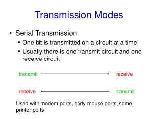
Communication Modes • 3 common communication modes are simplex, half-duplex and duplex. • Simplex: Transmit in one direction. For e.g. a radio station broadcasting and data logging system • Half-duplex: Two interconnected devices exchanges information (data) alternately For e.g. a “walkie-talkie” • Duplex: To interconnected devices transmit and receive simultaneously. A telephony system
Transmission modes • 2 Types: • Asynchronous • Synchronous • Data can be transmitted between two terminal equipment (DTE) in multiples of a fixed-length unit, • computer must be able to decode the messages of the fixed-length unit correctly. To do this it must know: • The bit rate being used (time duration of each bit), clock synchronization, • The start and end of each element, byte sync, • The start and stop of each complete message block or frame, frame sync.
Asynchronous transmission • data are generated at random intervals, e.g. typing on a keyboard of a computer. • Signal on the transmission line will be in the idle (off) state for long time intervals. • It is necessary for the receiver to resynchronize at the beginning of each character. • This is done by adding additional bits to the beginning and end ( start and stop bits respectively) to encapsulate the original data bits.
The polarity of start and stop bits are opposite to ensure at least one transition between each successive character. • Figure indicates that to transmit an 8 bit data, a total of 10 bits (for I start and I stop bit) or 11 bits (for I start and 2 stop bits) are utilized
Synchronous transmission • There is no need for a start bit and stop bit(s) for each character in synchronous transmission. • It can be a more efficient method of transmitting serial data • The receiver and the transmitter are synchronized • Large block of data characters one after the other are sent with no time intervals between characters. • The receiver automatically knows that every 8 bits received after synchronization represents a data character. • When data is not being sent through a synchronous data link the line is held in a marking condition.
The transmitter sends out one or more unique characters called SYNC characters or a unique bit pattern called a flag to mark the start of transmission • The receiver uses the SYNC/ flag characters to synchronize its internal clock with that of the transmitter. • The transmitter then shifts in the and converts them to parallel form for the computer. • Frequently used in high speed modems and digital communication channels. • There will be some control characters after the SYNC characters and before the END character. • Two ways of organizing a synchronous data link : Character (or byte) oriented and bit oriented.
Character oriented scheme • Made up of a variable number of 7- or 8-bit character • Transmitted as a contiguous string of binary bits with no delay between them. • The receiving device therefore having achieved clock synchronism must be able to: • 1. detect the start and end of each character (character synchronism) and • 2. detect the start and end of each complete frame (frame synchronism). • The main aim of which is to make synchronization process independent of the actual contents of a frame. • This type of synchronization scheme is said to be transparent / data transparent • Used in the binary synchronous control protocol (BSC) known as Basic Mode ( will be covered later).
Character synchronization - transmitter sending two/more SYNC characters at start each transmitted frame. • The receiver by scanning the received bit stream until it detects the know pattern of the SYNC character to achieve character synchronization. • Additional precaution must be taken to ensure that the end-of-frame termination character (ETX) is not present within the frame content • To achieve this a pair of characters is used both to signal the start and end of a frame as shown Figure • character (or byte) stuffing - To avoid abnormal termination due to the frame contents containing the end-of-frame character sequence, the transmitter inserts a second data link escape (DLE) character into the transmitted data streams whenever it detects a DLE character in the contents of the frame. • End of frame is a unique DLE-ETX sequence.
Bit oriented scheme • Each transmitted frame may contain an arbitrary number of bits • The opening and closing flags fields indicating the start and end of the frame are the same (0111111 0). • To achieve data transparency it is necessary to ensure that the flag sequence is not present in the frame contents. • Bit stuffing - The transmitter detects whenever there is a sequence of 5 contiguous binary 1 digits and automatically inserts an additional binary 0. • Flag sequence 0 1 1 1 1 1 1 0 can never be transmitted between opening and closing flags. • Commonly used in high data link control (HDLC).
LSI Device for Serial Communications • Universal Synchronous Asynchronous Receiver and Transmitter or USART is used to support asynchronous transmission. • It is a programmable device and a user can, by simply loading a predefined control word (bit pattern) into the device, specifying the required operating characteristics. • User initializes by loading with the required bit pattern to define the required operating characteristics. • Operating characteristics are the data units, 5,6,7, or 8 bits/characters, odd or even parity or non, one or more stop bits and the bit rates for transmission and reception.
Sending and Receiving characters asynchronously using the 8251A • Data characters can be sent to and read from the 8250 on an interrupt basis or on a polled basis. • Transmit a character on a polled basis, the 8250 status register is read and checked over and over again until the Tranmitter buffer empty bit (D0) is found to be 1. • A data character is then written to the 8250 data address. • Reading a character a polled basis is a similar process, except that the data ready bit (D0) of the status register is polled to determine when a character is ready to be read. Status register bit D1, D2, and D3 can be checked to see if a parity error, overrun or a framing error has occurred.