Download
1 / 24
501 likes | 1.37k Views
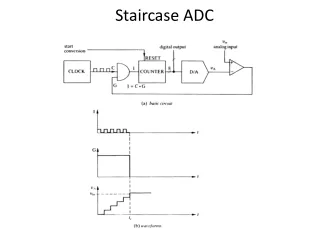
Oversampling ADC. Nyquist -Rate ADC. The “black box” version of the quantization process Digitizes the input signal up to the Nyquist frequency ( f s /2) Minimum sampling frequency ( f s ) for a given input bandwidth Each sample is digitized to the maximum resolution of the converter.

E N D
Nyquist-Rate ADC • The “black box” version of the quantization process • Digitizes the input signal up to the Nyquist frequency (fs/2) • Minimum sampling frequency (fs) for a given input bandwidth • Each sample is digitized to the maximum resolution of the converter
Anti-Aliasing Filter (AAF) • Input signal must be band-limited prior to sampling • Nyquist sampling places stringent requirement on the roll-off characteristic of AAF • Often some oversampling is employed to relax the AAF design (better phase response too) • Decimation filter (digital) can be linear-phase
Oversampling ADC • Sample rate is well beyond the signal bandwidth • Coarse quantization is combined with feedback to provide an accurate estimate of the input signal on an “average” sense • Quantization error in the coarse digital output can be removed by the digital decimation filter • The resolution/accuracy of oversampling converters is achieved in a sequence of samples (“average” sense) rather than a single sample; the usual concept of DNL and INL of Nyquist converters are not applicable
Relaxed AAF Requirement • Nyquist-rate converters • Oversampling converters OSR = fs/2fm Band-pass oversampling Sub-sampling
Oversampling ADC • Predictive type • Delta modulation • Noise-shaping type • Sigma-delta modulation • Multi-level (quantization) sigma-delta modulation • Multi-stage (cascaded) sigma-delta modulation (MASH)
Oversampling Nyquist Oversampled OSR = M
Noise Shaping Push noise out of signal band Large gain @ LF, low gain @ HF → Integrator?
Sigma-Delta (ΣΔ) Modulator First-order ΣΔ modulator • Noise shaping obtained with an integrator • Output subtracted from input to avoid integrator saturation
Linearized Discrete-Time Model Caveat: E(z) may be correlated with X(z) – not “white”!
First-Order Noise Shaping Doubling OSR (M) increases SQNR by 9 dB (1.5 bit/oct)
SC Implementation • SC integrator • 1-bit ADC → simple, ZX detector • 1-bit feedback DAC→ simple, inherently linear
Second-Order ΣΔ Modulator Doubling OSR (M) increases SQNR by 15 dB (2.5 bit/oct)
2nd-Order ΣΔ Modulator (1-Bit Quantizer) • Simple, stable, highly-linear • Insensitive to component mismatch • Less correlation b/t E(z) and X(z)
Generalization (Lth-Order Noise Shaping) • Doubling OSR (M) increases SQNR by (6L+3) dB, or (L+0.5) bit • Potential instability for 3rd- and higher-order single-loop ΣΔ modulators
ΣΔ vs. Nyquist ADC’s ΣΔ ADC output (1-bit) Nyquist ADC output • ΣΔ ADC behaves quite differently from Nyquist converters • Digital codes only display an “average” impression of the input • INL, DNL, monotonicity, missing code, etc. do not directly apply in ΣΔ converters → use SNR, SNDR, SFDR instead
Tones • The output spectrum corresponding to Vi = 0 results in a tone at fs/2, and will get eliminated by the decimation filter • The 2nd output not only has a tone at fs/2, but also a low-frequency tone – fs/2000 – that cannot be eliminated by the decimation filter
Tones • Origin – the quantization error spectrum of the low-resolution ADC (1-bit in the previous example) in a ΣΔ modulator is NOT white, but correlated with the input signal, especially for idle (DC) inputs. (R. Gray, “Spectral analysis of sigma-delta quantization noise”) • Approaches to “whitening” the error spectrum • Dither – high-frequency noise added in the loop to randomize the quantization error. Drawback is that large dither consumes the input dynamic range. • Multi-level quantization. Needs linear multi-level DAC. • High-order single-loop ΣΔ modulator. Potentially unstable. • Cascaded (MASH) ΣΔ modulator. Sensitive to mismatch.
Cascaded (MASH) ΣΔ Modulator • Idea: to further quantize E(z) and later subtract out in digital domain • The 2nd quantizer can be a ΣΔ modulator as well
2-1 Cascaded Modulator • E1(z) completely cancelled assuming perfect matching between the modulator NTF (analog domain) and the DNTF (digital domain) • A 3rd-order noise shaping on E2(z) obtained • No potential instability problem
Integrator Noise INT1 dominates the overall noise Performance! Delay ignored
References • B. E. Boser and B. A. Wooley, JSSC, pp. 1298-1308, issue 6, 1988. • B. H. Leung et al., JSSC, pp. 1351-1357, issue 6, 1988. • T. C. Leslie and B. Singh, ISCAS, 1990, pp. 372-375. • B. P. Brandt and B. A. Wooley, JSSC, pp. 1746-1756, issue 12, 1991. • F. Chen and B. H. Leung, JSSC, pp. 453-460, issue 4, 1995. • R. T. Baird and T. S. Fiez, TCAS2, pp. 753-762, issue 12, 1995. • T. L. Brooks et al., JSSC, pp. 1896-1906, issue 12, 1997. • A. K. Ong and B. A. Wooley, JSSC, pp. 1920-1934, issue 12, 1997. • S. A. Jantzi, K. W. Martin, and A.S. Sedra, JSSC, pp. 1935-1950, issue 12, 1997. • A. Yasuda, H. Tanimoto, and T. Iida, JSSC, pp. 1879-1886, issue 12, 1998. • A. R. Feldman, B. E. Boser, and P. R. Gray, JSSC, pp. 1462-1469, issue 10, 1998. • H. Tao and J. M. Khoury, JSSC, pp. 1741-1752, issue 12, 1999. • E. J. van der Zwan et al., JSSC, pp. 1810-1819, issue 12, 2000. • I. Fujimori et al., JSSC, pp. 1820-1828, issue 12, 2000. • Y. Geerts, M.S.J. Steyaert, W. Sansen, JSSC, pp. 1829-1840, issue 12, 2000.
References • T. Burger and Q. Huang, JSSC, pp. 1868-1878, issue 12, 2001. • K. Vleugels, S. Rabii, and B. A. Wooley, JSSC, pp. 1887-1899, issue 12, 2001. • S. K. Gupta and V.Fong, JSSC, pp. 1653-1661, issue 12, 2002. • R. Schreier et al., JSSC, pp. 1636-1644, issue 12, 2002. • J. Silva et al., CICC, 2002, pp. 183-190. • Y.-I. Park et al., CICC, 2003, pp. 115-118. • L. J. Breems et al., JSSC, pp. 2152-2160, issue 12, 2004. • R. Jiang and T. S. Fiez, JSSC, pp. 63-74, issue 12, 2004. • P. Balmelli and Q. Huang, JSSC, pp. 2161-2169, issue 12, 2004. • K. Y. Nam et al., CICC, 2004, pp. 515-518. • X. Wang et al., CICC, 2004, pp. 523-526. • A. Bosi et al., ISSCC, 2005, pp. 174-175. • N. Yaghini and D. Johns, ISSCC, 2005, pp. 502-503. • G. Mitteregger et al., JSSC, pp. 2641-2649, issue 12, 2006. • R. Schreier et al., JSSC, pp. 2632-2640, issue 12, 2006.