Download
1 / 15
150 likes | 247 Views
MQY as Q5 in the HL LHC era. Glyn Kirby. MQY 001 bat 927. Overview. MQY parameter list Proposed change to LHC circuit High Energy in test station comparison Test station modification PSU’s set up, current leads 3 or 4, protection. Test plan Typical out of balance powering.

E N D
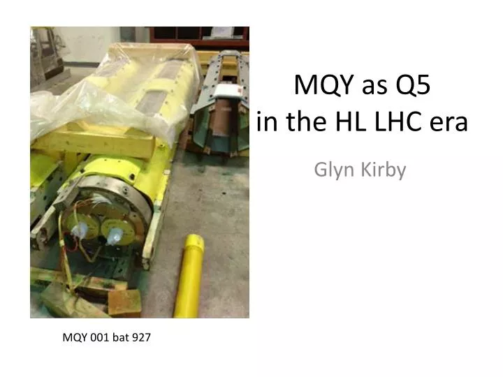
MQY as Q5 in the HL LHC era Glyn Kirby MQY 001 bat 927
Overview • MQY parameter list • Proposed change to LHC circuit • High Energy in test station comparison • Test station modification • PSU’s set up, current leads 3 or 4, protection. • Test plan • Typical out of balance powering
MQY parameters • Operating Temp 4.5 K 1.9 K • Nom Gradient 160 T/m 200T/m • Nom Current 3610 A 4500 A • Inductance 74 mH/aperture • Twin aperture clear 70mm diameter • Overall length 3.64 m • Mass 4.3 tones
Comparing Quench Energy’s • MQXC 12.8KA, 688 kJ • HQ. 16.2 KA, 735 kJ • MQY 4.5 K , 3.61 kA, 482 kJ/ap. 964 kJ 160 T/m • MQY 1.9 K , ultime performance 110% of nominal gradient, 5.0 kA and 220 T/m, 950 kJ /Ap. 1900 kJ
Operating Area 5000 A, 5000A 2000 kJ 1.9K 958 kJ 4.5K 4500 A, 2250 A 936 kJ 50% diff HQ 750 kJ 90 % diff field measurement ? 934 kJ 3600 A 5030 A
Standard Circuit in LHC Std PSU in LHC is limited to I2=50% I1
SM18 Test set up ? Ideal set up 4 current leads Two dumps Two switches QPS set up ? PSU1 4500 A PSU2 2250 A Or use quench heaters to protect magnet
Test cycles 50% A1/A2 MAX A1-A2 90% A1/A2 Example of the type of cycle we will need. Slow ramp rates 3.8 A/s ~ 20 mins ramp. Staircase with field measurement every 500 A in both apertures 1 hr flat top at max field / current configuration Check joints, may need to open up part of the joint box to get V-taps in? Three machine cycles!
MQY Test project • MQY ? • Mount current lead-box on magnet, for independent powering? • Electrical testing • Quench heaters (insulation , discharge) • Magnet Ground insulation • Field Measurements ? • Cold testing.
Cold testing • Set up rotating field probes in both apertures? • Std. electrical checks. • Cool down 4.3 tonnes larger than MQ. 3 days? • Set up QPS • Test field measurement. 1 day, may be more? • Training 1.9 K, 4 quenches a day ? 2 days • 50% and 90% A1/A2 at 4.5 kA 2.25 kA & ?/? • Field measurement with 50% diff. 2 days • QLIQ test , reconfigure onto one PSU. ? Simulation needed! • Warm up, thermal cycle ?. • Total 12 to 15days
Conclusions / Comments • Two power supplies, control set up needed • High energy , carful pre testing to predict pressure and limit it! • Field measurement two rotating probes, or only measure one aperture, or thermal cycle to be abler to measure both apertures at all currents. • Two to three week testing >>>>>>>>>>>>>>>> • Joint tests after siting in air for 7 to 10 year’s? open joint box and have a look! • Should we also test MQM?