Download
1 / 54
540 likes | 660 Views
VirtuLab : Web Based Flow Visualization Facility. Final Presentation Team 6 Members : Justin Scott Karen Davis Sydni Credle. Mentor/Client : Professor : Dr. Shih Dr.Luongo. December 7, 2000. Overview. Client Statement Background Information Specifications

E N D
VirtuLab: Web Based Flow Visualization Facility Final Presentation Team 6 Members: Justin Scott Karen Davis Sydni Credle Mentor/Client: Professor: Dr. Shih Dr.Luongo December 7, 2000
Overview • Client Statement • Background Information • Specifications • Camera Mount Design • Work Breakdown Structure (WBS) • Scheduling • Complications and Solutions • Goals for the Spring Semester • Conclusion
Conclusion • WBS and Schedule promoted team efficiency towards completion of project goals. • Camera mount design and fabrication were priority this semester. Upon completion, testing and calibration can be performed. • Team members now have an extensive working knowledge of the LabVIEW software.
Conclusion (cont’d) • In developing the user interface, the major concern for team has been the "how" of the matter.
Web-Based Flow Visualization Facility (WBFVF) Work Breakdown Structure (WBS)
Project Schedule Spring Semester Goals
Goals for the Spring Semester Web Page Design • Incorporate LabVIEW programming into design • Embed live video streaming • Background and procedure for experiment • Upload class deliverables for public use
Spring Semester Goals (continued) LabVIEW • Acquire LabVIEW version 6.i • Train team members to use 6.i • Final experiment interface design (educational module) • Consolidate motor controller functions into one program • Control via the Internet
Spring Semester Goals (continued) VC-C4 Web Cam • Order and acquire the VC-C4 camera from Canon, Inc. • Train team members to use VC-C4 web cam software • Create LabVIEW program to automate the control of the web cam • Research WebVIEW software
Spring Semester Goals (continued) Existing Experiment Set-up • Preliminary test of system • Performance Analysis • Design Modifications • Calibration • Final Testing
Complications and Solutions • LabVIEW • Received older version, 5.1, when we were supposed to receive 6.i. • Contacted manufacturer, National Instruments, to rectify the situation (coming soon). • Unfamiliar with the LabVIEW programming language. • Group members trained by attending instructional seminars, using tutorial CDs and utilizing local COE users.
Complications and Solutions (cont’d) • VC-C3 Camera • Through research, we found it was too expensive. • Ordered interim software and components (Intel Camera and Microsoft NetMeeting Software). • Recently received client approval to order the VC-C4 version of the camera.
Complications and Solutions (cont’d) • Web Page (live video streaming) • Underestimation of the task at hand. • Actively sought out professionals • Dr. Van Dommelen • Third floor Webmasters • NetMeeting representatives
Objectives/Client Statement • Design and build a towing tank facility and the associated imaging process. • Provide visualization enhanced information to supplement the teaching of fluid mechanics. • Create computer interfaced instrument control for remote operation via the Internet.
Introduction • Learning/teaching Thermal Fluids is complex. • Distance learning purposes • Pre-lab student aid • Master each component separately • Move at own pace • Real world applications
Background Information • A “fluid” is a substance that readily flows under applied shear (gases, liquids i.e. water, alcohol, gasoline). • Fluids can’t be detected by the human eye, therefore, the concepts behind fluid mechanics prove to be very difficult to learn. • Use of flow visualization to take out the guess work from the phenomena.
Remote Users Physical Laboratory System Set-up (motor controller) LabVIEW Interface
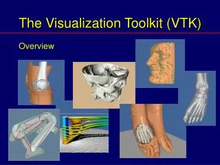
What is LabVIEW? • Laboratory Virtual Instrument Engineering Workbench • Automation and Control of Equipment • “G-programming” • Creation of programs using graphics • Pictorial Block Diagrams instead of long lines of syntax • Straightforward data flow methodology
LabVIEW User Interface • “Front Panel” • Knobs, Buttons, graphs, etc. • User Input using mouse and keyboard • Graphical Code • “Block Diagram” • Constants, built-in functions, program execution control structures • Wires denote data flow
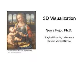
Simple example: Ideal cylinder Vs. Real world cylinder • Ideal circular cylinder experiencing 2-D flow of a uniform stream • Figure (left) shows symmetrical stream lines and no drag force. • Real circular cylinder experiencing a non-uniform flow • Figure (right) depicts the flow separation, creating a wake
Schematic diagram illustrating basic setup of web-based flow visualization system.
Mechanical Design Aspects • Design of mobile camera mounts • Design of synchronous linkage for laser/optical platform • Motor Selection • Linear bearing system
Mechanical Design Aspects (continued) • Gear Analysis • Loading Calculations • Material Selection and Design • Plumbing Design • Setup and design of video recording equipment
Computer Related Aspects • Remote instrument control via the Internet using LabVIEW programming • Video studio design for the lab imaging • Real time video and data streaming via the Internet
System Configuration Motor Camera mount location Towing Tank Web Cam Location Motor Controller
Camera Mount Design Needs • Easily manufactured • Cost efficient • Lightweight • Easily used
Camera Mount Design Needs (Continued) • Capable of supporting camera • Appearance uniform with existing equipment • Locking mechanism • Long lasting
Pin/Slider Dovetail 2 Track Easily manufactured + -- + Cost efficient + -- + Lightweight + -- -- Easily used -- + + Capable of supporting camera -- + + Appearance uniform w/ existing equipment -- -- + Locking mechanism included -- + + Long lasting -- + + Total Positive 3 4 7 Specifications for the Camera Mount
Detailed Concept Design • Dimensions • Locking mechanism design • Materials used • Specific cost
Existing Camera Mount Adjustable Pole Camera Mount Location
Work Breakdown Structure • Project Management Activities • Refinement of Client Statement • Web Camera • Imaging Camera Mount • LabVIEW - Motor Controller • Simulation/Testing • Web Page Publishing
Project Management • Development of project plans • Weekly Design Team Meetings (2) • Bi-weekly client meetings • Progress Reports for client • Refinement of project plans
Refinement of Client Statement • Clarify customer statement completed • Research prior designs ongoing • Review with client completed
Web Camera • Research software and equipment completed (VC-C3 camera and WebVIEW software = $) • Order interim software and components completed (Intel Camera and Microsoft Netmeeting Software) • Performance tests (Teleconference) completed • Design of system setup • Intranet/Internet capability testing
Imaging Camera Mount • Concept Generation completed • Design Selection completed • Final Design Review completed • Fabrication: ongoing • Ordering materials and components • Assembly
LabVIEW - Motor Controller • LabVIEW • Software Acquisition completed • Introduction to software ongoing • Tutorials • Attend educational seminars (Nov. 9-Orlando, Fl) • Design of the User Interface ongoing • Motor Controller • Introduction to motor controller ongoing • Velocity Profile Manipulation ongoing • Programming using LabVIEW ongoing
Simulation/Testing of Towing Tank • Preliminary test of existing system pending • Performance Analysis pending • Design Modifications pending • Final Testing pending • Calibration pending
Web Page Publishing • Concept Generation ongoing • Design Selection ongoing • Final Web Design ongoing
Work Breakdown Structure • Project Management Activities • Refinement of Client Statement • Web Camera • Imaging Camera Mount • LabVIEW - Motor Controller • Simulation/Testing • Web Page Publishing
Project Update • National Instruments “NI Days” Convention (Orlando, FL - 11/9/00) • Product Overview • LabVIEW 6.i • Software/Hardware Capabilities • Monitoring and Control Over the Web • Contacts • Received New LabVIEW Software
Project Update (continued) • Consultation with Dr. Van Dommelen • Web Page • Basic Design Layout • Media Data Streaming (Audio/Video) • Project Deliverables • Exchange a left-hand threaded component with a right-hand threaded component.
Tentative Final Design Contents • Background Theory/Introduction • Project Scope • Specifications • Design Review • WBS/Scheduling • WBFVF Web Page • Meeting Log • Correspondence • Spring Project Plans
Acknowledgements/Bibliography • Davis, K., Scott J., and S. Credle, Senior Design Proposal: Web Based Flow Visualization Facility, FAMU-FSU College of Engineering, Tallahassee, 2000. • FloWorks, Engineering Fluid Dynamics for SolidWorks, www.floworks.com, 2000. • White, F. M., Viscous Fluid Flow, McGraw-Hill, New York, 1974.
Conclusion • Completed flow visualization system is a critical tool in the analysis of fluid mechanics. • Integration of the physical laboratory with the Internet, in turn creates a virtual laboratory. • The final deliverable will benefit educators, students, and industry.
Conclusions • Comprehension of problem statement has been achieved • Upon of completion of camera mount fabrication, can proceed with simulation/testing of the towing tank • Next: Modifying and calibrating the existing system