Download
1 / 8
80 likes | 205 Views
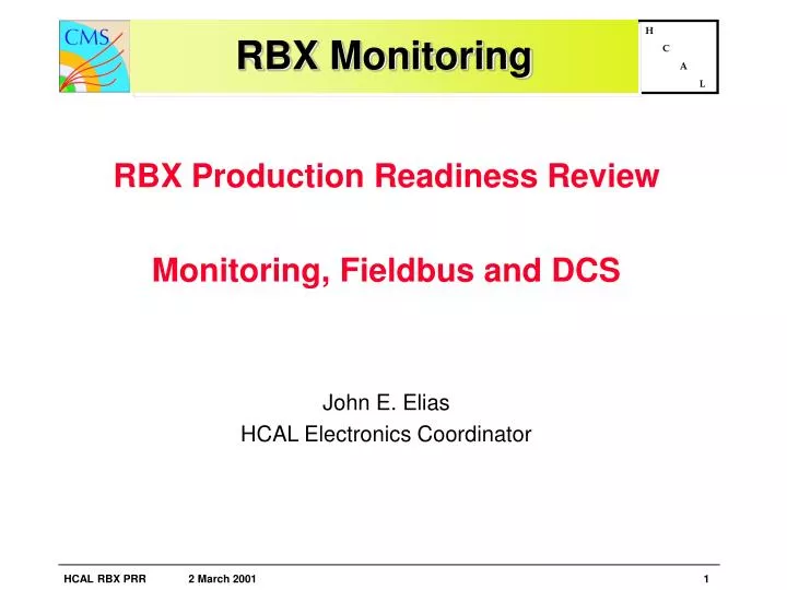
RBX Monitoring. RBX Production Readiness Review Monitoring, Fieldbus and DCS John E. Elias HCAL Electronics Coordinator. Architecture of the CMS control system (functional block diagram):. Communi cation with sub detector controllers. Standard slow control. Subdetector 2 controller.

E N D
RBX Monitoring • RBX Production Readiness Review • Monitoring, Fieldbus and DCS • John E. Elias • HCAL Electronics Coordinator
Architecture of the CMS control system (functional block diagram): Communi cation with sub detector controllers Standard slow control Subdetector 2 controller DB Selection of runtype resource manager (selection of needed resources) RunCTRL ext.communication(LHC,infrastructure,magnet, safety,…) DAQ, Trigger Supervisory System SCADA System Supervision of subdetector controllers Device Server Request to download and read of constants and programs LAN(ethernet) Classsical slow control (OPC, others) fieldbus (CAN, Profibus, ..) DB Subdetector 1 controller fieldbusdevices, PLCs, VME, HV+LVpower supplies Devices Downloading and reading of constants and programs Calibration events (T, laser, …) Sensors, Actuators FE electronics 2 11/02/2000 Wolfgang Funk -CERN CMS
Clock and Control Module • One clock and control module per RBX • Star configuration, not daisy chained • Control functions • Download the Channel Control ASICs • Readback (verify) the Channel Control ASICs • Configure the TTC Rx • Readback the electronics temperatures • Readback the low voltage supply values • Execute master reset on command • Translate between fieldbus and RBX serial bus
Design Basis • Proven CAN bus technology • ATLAS Tile Calorimeter • ATLAS DCS • Radiation tolerance • http://atlas.web.cern.ch/Atlas/GROUPS/FRONTEND/radhard.htm#Content • http://radhome.gsfc.nasa.gov/top.htm • http://www.national.com/appinfo/milaero/ • http://www.xilinx.com/partinfo/military.pdf • Part availability
Summary • Monitor and control integrated with DCS • Joint Controls Project team at CERN provides hardware and software support for CAN bus • Client/server interface to the official SCADA, PVSS II, to be done by DUBNA collaborators • Engineering • Development platform for CAN is LabView • Principal challenge is implementing the functional block diagram using radiation tolerant COTS – the design may not be as simple and elegant as it could be otherwise • Prototype milestone is July 2001