Download
1 / 3
30 likes | 112 Views
Test Site #1 Solar array and trailer. Engine Efficiency. Power Output BTU’s of Fuel. Battery Voltage Engine Power Output. Hydrogen Power System for Remote Applications. Rick Purcell Associate Research Mechanical Engineer. Kirk Collier Collier Technologies. Curt Robbins

E N D
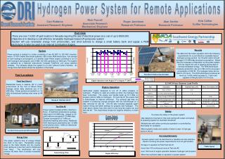
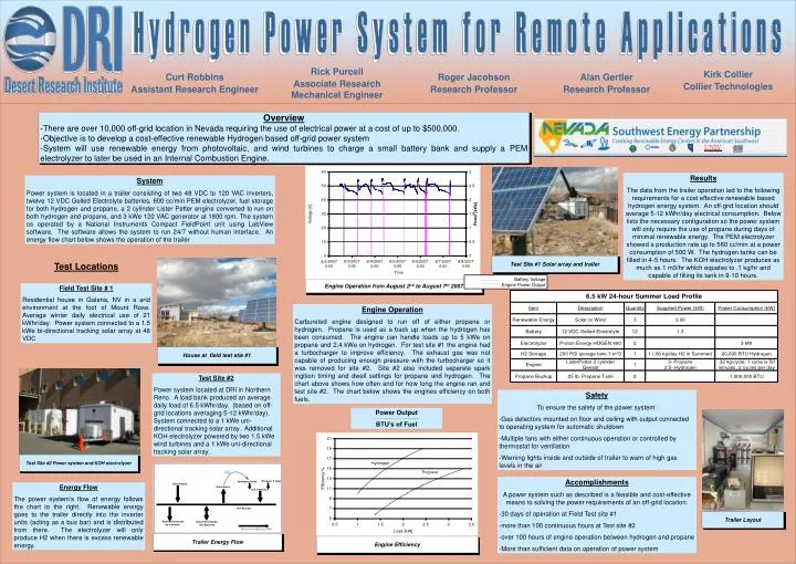
Test Site #1 Solar array and trailer Engine Efficiency Power Output BTU’s of Fuel Battery Voltage Engine Power Output Hydrogen Power System for Remote Applications Rick Purcell Associate Research Mechanical Engineer Kirk Collier Collier Technologies Curt Robbins Assistant Research Engineer Roger Jacobson Research Professor Alan Gertler Research Professor Overview -There are over 10,000 off-grid location in Nevada requiring the use of electrical power at a cost of up to $500,000. -Objective is to develop a cost-effective renewable Hydrogen based off-grid power system -System will use renewable energy from photovoltaic, and wind turbines to charge a small battery bank and supply a PEM electrolyzer to later be used in an Internal Combustion Engine. Results The data from the trailer operation led to the following requirements for a cost effective renewable based hydrogen energy system. An off-grid location should average 5-12 kWhr/day electrical consumption. Below lists the necessary configuration so the power system will only require the use of propane during days of minimal renewable energy. The PEM electrolyzer showed a production rate up to 560 cc/min at a power consumption of 500 W. The hydrogen tanks can be filled in 4-5 hours. The KOH electrolyzer produces as much as 1 m3/hr which equates to .1 kg/hr and capable of filling its tank in 9-10 hours. System Power system is located in a trailer consisting of two 48 VDC to 120 VAC inverters, twelve 12 VDC Gelled Electrolyte batteries, 600 cc/min PEM electrolyzer, fuel storage for both hydrogen and propane, a 2 cylinder Lister Petter engine converted to run on both hydrogen and propane, and 3 kWe 120 VAC generator at 1800 rpm. The system os operated by a National Instruments Compact FieldPoint unit using LabView software. The software allows the system to run 24/7 without human interface. An energy flow chart below shows the operation of the trailer Test Locations Engine Operation from August 2nd to August 7th 2007 Field Test Site # 1 Residential house in Galena, NV in a arid environment at the foot of Mount Rose. Average winter daily electrical use of 21 kWhr/day. Power system connected to a 1.5 kWe bi-directional tracking solar array at 48 VDC Engine Operation Carbureted engine designed to run off of either propane or hydrogen. Propane is used as a back up when the hydrogen has been consumed. The engine can handle loads up to 5 kWe on propane and 2.4 kWe on hydrogen. For test site #1 the engine had a turbocharger to improve efficiency. The exhaust gas was not capable of producing enough pressure with the turbocharger so it was removed for site #2. Site #2 also included separate spark ingition timing and dwell settings for propane and hydrogen. The chart above shows how often and for how long the engine ran and test site #2. The chart below shows the engines efficiency on both fuels. House at field test stie #1 Test Site #2 Power system located at DRI in Northern Reno. A load bank produced an average daily load of 6.5 kWhr/day. (based on off-grid locations averaging 5-12 kWhr/day). System connected to a 1 kWe uni-directional tracking solar array. Additional KOH electrolyzer powered by two 1.5 kWe wind turbines and a 1 kWe uni-directional tracking solar array. Safety To ensure the safety of the power system: -Gas detectors mounted on floor and ceiling with output connected to operating system for automatic shutdown -Multiple fans with either continuous operation or controlled by thermostat for ventilation -Warning lights inside and outside of trailer to warn of high gas levels in the air Test Site #2 Power system and KOH electrolyzer Accomplishments A power system such as described is a feasible and cost-effective means to solving the power requirements of an off-grid location. -30 days of operation at Field Test site #1 -more than 100 continuous hours at Test site #2 -over 100 hours of engine operation between hydrogen and propane -More than sufficient data on operation of power system Energy Flow The power system’s flow of energy follows the chart to the right. Renewable energy goes to the trailer directly into the inverter units (acting as a bus bar) and is distributed from there. The electrolyzer will only produce H2 when there is excess renewable energy. Trailer Layout Trailer Energy Flow
Hydrogen Power System for Remote Applications Test Sites 1. Residential field location at 21 kWhr/day 2. DRI facility at 6.5 kWhr/day