Download
1 / 30
300 likes | 486 Views
Noise and Power Tradeoffs in CMOS Front Ends. Paul O’Connor. Acknowledgements. Gianluigi De Geronimo Veljko Radeka Angelo Dragone Jean-Fran ç ois Pratte. Outline. Fundamental limits Constrained noise optimization power speed Figure of merit analog digital Architecture choices

E N D
Noise and Power Tradeoffs in CMOS Front Ends Paul O’Connor
Acknowledgements • Gianluigi De Geronimo • Veljko Radeka • Angelo Dragone • Jean-François Pratte VIth International Meeting on Front End Electronics Paul O'Connor BNL May 18, 2006
Outline • Fundamental limits • Constrained noise optimization • power • speed • Figure of merit • analog • digital • Architecture choices • Summary VIth International Meeting on Front End Electronics Paul O'Connor BNL May 18, 2006
What are the fundamental limits? • Charge of one electron ENC ≥ 1 electron rms? VIth International Meeting on Front End Electronics Paul O'Connor BNL May 18, 2006
What are the fundamental limits? • Uncertainty principle? DE·Dt ≥ ħ/2 e.g., Cd=1pF, tp=1ms DQ ≥ 0.06 e- VIth International Meeting on Front End Electronics Paul O'Connor BNL May 18, 2006
What are the fundamental limits? • Thermal fluctuations? e.g., at 300K: Cd ENC 0.1pF 126 e- 1 400 10 1260 VIth International Meeting on Front End Electronics Paul O'Connor BNL May 18, 2006
What are the fundamental limits? • Channel thermal noise (wT depends on power and level of inversion) e.g., wT = 1GHz, tp = 1ms, Cd=1pF ENCt > 25 e- VIth International Meeting on Front End Electronics Paul O'Connor BNL May 18, 2006
What are the fundamental limits? • Low frequency (1/f) noise e.g., Kf = 10-24J, Cd=1pF ENCf > 16 e- VIth International Meeting on Front End Electronics Paul O'Connor BNL May 18, 2006
Most systems are power-constrained • particle physics services/cooling/material • space limited power sources • security (portable) limited power sources • imaging power density/cooling VIth International Meeting on Front End Electronics Paul O'Connor BNL May 18, 2006
Shaping time is not always a free choice tp may be constrained by • pileup • timing precision • ballistic deficit • parallel noise (noise corner time constant √RsRpCin2) VIth International Meeting on Front End Electronics Paul O'Connor BNL May 18, 2006
How can power be reduced without sacrificing performance (SNR, pileup)? • design: • optimize M1 and H(s) • technology: • scaling impact on noise and dynamic range • architecture: • multiplexing and digitizing strategy VIth International Meeting on Front End Electronics Paul O'Connor BNL May 18, 2006
Input transistor (M1) optimization • Optimize for total (white + 1/f) series noise: • adjust W,L while holding Id and tp constant • Correct modeling of weak, moderate, and strong inversion (EKV model): • dependence of gm, Cg, g on operating point • Low-frequency noise: • dependence on Lg • spectral dependence • Predict result of scaling to new technologies P. O’Connor, Proc. FEE2003 Snowmass G. De Geronimo, P. O’Connor, TNS52(6),3223 (2005) VIth International Meeting on Front End Electronics Paul O'Connor BNL May 18, 2006
White + 1/f noise vs. M1 power Transistor width optimized for each configuration vs. peaking time vs. detector capacitance Cd=1pF tp=1ms VIth International Meeting on Front End Electronics Paul O'Connor BNL May 18, 2006
Noise models compared Simple 1/f noise model More accurate 1/f noise model Nch Pch TSMC 0.25mm process Cd = 1pF tp = 1ms VIth International Meeting on Front End Electronics Paul O'Connor BNL May 18, 2006
Choice of filter function Shaper Characteristics VIth International Meeting on Front End Electronics Paul O'Connor BNL May 18, 2006
BALLISTIC DEFICIT High-order shaper improvements • add shaper poles • improve symmetry • longer tp for same tw, lower noise • small increase in shaper power • power does more good here than in M1! • area penalty 0.25mm CMOS Cd=1pF tw=100ns VIth International Meeting on Front End Electronics Paul O'Connor BNL May 18, 2006
Figure of merit for charge amplifiers • Expresses the power cost of achieving SNR and speed • Can be applied to front ends in any technology • Corresponds to figure of merit for analog-digital converters: • Provides guidance for low-power system design VIth International Meeting on Front End Electronics Paul O'Connor BNL May 18, 2006
1.5pJ Figure of merit for charge amplifiers (FOMCSA) vs. detector capacitance Medipix-2 Llopart et al., TNS49(2002)2279 PSI-46 Erdmannt et al., NIMA549(2005)153 VIth International Meeting on Front End Electronics Paul O'Connor BNL May 18, 2006
2.8pJ Figure of merit for ADCs (FOMADC) vs. dynamic range VIth International Meeting on Front End Electronics Paul O'Connor BNL May 18, 2006
Architecture choices • Digital waveform recording of every channel requires ADC to have: • same SNR as charge amplifier • sampling frequency 2X – 20X higher than analog bandwidth • GuaranteesPADC >> PCSA • Better architecture: capture and buffer the analog information on the FEE ASIC, then steer samples to the ADC • Switched capacitors or peak detectors can serve as the sampling cells • Use analog buffers (memory) with simultaneous READ/WRITE to avoid deadtime VIth International Meeting on Front End Electronics Paul O'Connor BNL May 18, 2006
digital waveform record tp Epk TOT event-to-event time trigger thr. cross Analog vs. digital feature extraction VIth International Meeting on Front End Electronics Paul O'Connor BNL May 18, 2006
Analog storage and buffering schemes unbuffered buffered mux sample sampling on switched caps mux sampling on peak-detect caps VIth International Meeting on Front End Electronics Paul O'Connor BNL May 18, 2006
EXAMPLES VIth International Meeting on Front End Electronics Paul O'Connor BNL May 18, 2006
Rule-of-thumb estimates • Use FOMCSA ~ 1pJ, calculate most quantities of interest. • Given Pmax, rate r, what is achievable SNR? • e.g. P=1mW, r=100kHz, SNR ~ 103 • What power needed to get timing accuracy st? • e.g. st=2ns, P ~ 50mW VIth International Meeting on Front End Electronics Paul O'Connor BNL May 18, 2006
Front-End Electronics ~7300 channels ASIC Pads ~7300 Readout of a TPC using analog buffering TPC Chamber Double-GEM (gain ~ 500) Mini-TPC with GEM readout for LEGS experiment at BNL Anode Plane Gianluigi De Geronimo Jack Fried Anand Kandasamy Veljko Radeka Bo Yu VIth International Meeting on Front End Electronics Paul O'Connor BNL May 18, 2006
TPC Digitization Power • Npads 8000 • Ntimeslices 500 • Nvoxels 4x10⁶ • Digitization Energy (12 bit resolution): • 10-12J/bit * 212 * Nvoxels = 16 mJ • Power (FADC): • 16mJ / 7ms = 2000W (250 mW/chan) • Power (buffer and readout at 2 kHz trigger rate): • 16mJ / 500ms = 30W ( 4 mW/chan) • Compare with 0.75mW/chan for amplifier + 0.6mW/chan for PD + TAC. • With sparsified readout of only occupied channels buffered in PD: PADC ~ 0.6W (75 mW/chan). VIth International Meeting on Front End Electronics Paul O'Connor BNL May 18, 2006
Biparametric spectrum (signature) 241Am on CZT risetime energy Channel no. VIth International Meeting on Front End Electronics Paul O'Connor BNL May 18, 2006
Before correction After correction TOT measurement for pileup rejection Monochromatic 8keV X-rays on Si pad detector All data Exclude piled-up region VIth International Meeting on Front End Electronics Paul O'Connor BNL May 18, 2006
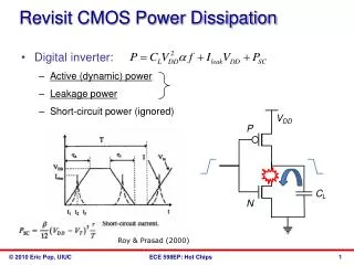
Summary • Noise is limited by available power and by the 1/f properties of the technology. • In addition to optimizing the first transistor, choice of shaping function is also important in noise optimization. • High-order shapers improve the power/noise tradeoff, and also improve pileup and charge collection performance. • An empirical figure of merit for charge amplifiers, analogous to that for ADCs, can be used to guide design choices. • Reducing the number of analog-to-digital conversions (where possible) improves noise by allowing power to be allocated to the front end. VIth International Meeting on Front End Electronics Paul O'Connor BNL May 18, 2006
VIth International Meeting on Front End Electronics Paul O'Connor BNL May 18, 2006