Download
1 / 15
180 likes | 336 Views
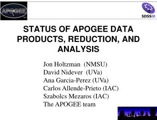
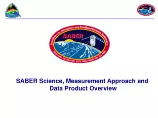
APOGEE Spectrograph Preliminary Design Review. OVERVIEW: APOGEE Data Reduction Pipeline Steven Majewski (and Science Team) Astronomy Department, UVa May 18-19, 2009 University of Virginia Charlottesville VA. Overview of Major Software Modules.

E N D
APOGEE Spectrograph Preliminary Design Review OVERVIEW: APOGEE Data Reduction Pipeline Steven Majewski (and Science Team) Astronomy Department, UVa May 18-19, 2009 University of Virginia Charlottesville VA
Overview of Major Software Modules APOGEE Quality Assurance (AQuA) Software (in real time) Raw data APOGEE Source Extraction and Calibration Software (ASECS) APOGEE Radial VelocityPipeline (ARVP) APOGEE Stellar Parameters and Chemical Abundance Pipeline (ASPCAP) Data Products External Calibration
Overview of Pipeline Personnel APOGEE PI Steven Majewski Project/Business ManagerFred Hearty SDSS3 Employee Science Team Science WorkingGroup Survey Scientist Ricardo Schiavon ASECS Matthew Shetrone ARVP Dmitry Bizyaev ASPCAP Carlos Allende-Prieto Calibration Peter Frinchaboy Software Postdoc 2Ana Elia Garcia Perez Software Postdoc 1David Nidever AQuA Pipeline Operator (BS1)Not hired yet 3 May 18, 2009
Raw data will consist of individual exposures, as follows: About 30 minutes each. Taken in one pair per visit to each field. Exposures in each pair offset in spectral dimension by 0.5 pixels to improve sampling. Three separate spectral pieces (one from each detector) From one to as many as ten to thirty visits to each field, driven by MARVELS coordination. Desire to probe more deeply in some fields. Limited accessibility to low declination fields. (Benefit, not driver: some RV variation sensitivity to binary companions.) No guarantee that same star will be in same fiber on different visits. Each visit will include fibers on sky and on hot stars (for telluric absorption monitoring). APOGEE Raw Data 4 May 18, 2009
Real time AQuA software assessment of data at the telescope: Presently least-developed module Anticipate making use of up-the-ramp accumulation of data cube tomonitor exposure levels/observing conditions Potential strategy: For each up-the-ramp readout (e.g., every ~10 seconds)… Quick extraction of all or some fraction of stellar spectra. Quantify exposure level at one or multiple wavelengths. Real time plot of exposure level versus source H-magnitude. Real time projection of remaining integration time needed to obtain neededS/N for faintest sources. Incorporate (slimmed down) elements of reduction pipeline APOGEE Quality Assurance Software 5 May 18, 2009
For each dither (~30 minute exposure): Up the ramp reduction from data cube to 2-D spectrum Used to overcome readout noise, cosmic rays and saturation issues. Must be created from scratch because all current versions (space-based) assume constant flux accumulation with time. Full fitting of data from 2-D spectrum to 1-D spectrum Required because of very tight packing of fibers. Will make use of knowledge of spatial profile of fibers, detailed optical(e.g., ZEMAX) model, scattered light model (including airglow lines), ghosts Will adapt the SDSS current “forward modeling” software. Wavelength solution Solve for CCD dither offset zero-point in pixels. Use airglow lines, supplemented with ThAr. Confirm the stable super solution is correct. Source Extraction and Calibration:Major Steps 6 May 18, 2009
For each dither (~30 minute exposure) - continued: Flat-field Remove pixel-to-pixel and fiber throughput variations. Obtained using “collimator-smeared” exposures of quartz lamp. Occasional sky flats used to check quartz/monitor instrument stability Sky subtraction Make use of 1-2 dozen simultaneously observed sky fibers per set-up. Must correct for sky background variations (spatially and temporally), bothin emission lines and continuum (separately). Telluric sky absorption correction Still unknown if spatial variations will be an issue. Use few simultaneously observed hot stars and knowledge from master telluric or atmospheric transmission models to solve for local telluric spectrum. Flux calibrate spectra Use most recent “acceptable” relative flux solution. Source Extraction and Calibration:Major Steps 7 May 18, 2009
For each dither (~30 minute exposure) - continued: Combine dithered pairs at each visit. Recover Nyquist-sampled 1-D spectra Solve for (using ARVP) and remove radial velocity offsets. Combine visits into single, high S/N spectrum (in three pieces) Remove velocity offsets from each visit Presumably produce a restframe spectrum Account for variation in pixel-to-wavelength mapping from each visit (resampling) individual PSF differences due to radial velocity differences and placement of the star on different fibers between visits. noise vector Source Extraction and Calibration:Major Steps 8 May 18, 2009
Every raw data cube will be stored in case future, better extraction methods are found. Also stored and passed on to other programs: Final wavelength-calibrated, telluric absorption/emission-corrected, sky-subtracted, relative flux calibrated 1-D spectra (in three wavelength/detector pieces) for: Individual exposures Dither-combined spectra for each visit Combined visit data at rest wavelength (if needed for ASPCAP) Each of the above will have an associated noise spectrum with propagated errors from each step. Each separate dither will have an associated spectral PSF for each pixel. The measured dither offset and derived radial velocity correction for each visit will also be stored. Source Extraction and Calibration:Output Products 9 May 18, 2009
For each visit, each star will have a derived RV and uncertainty. Considerations: Cross-correlation against either synthetic or actual observed templates. Three spectral pieces provide independent assessments. External calibration to RV standards. Iterate through ASPCAP to determine best template match. Search for RV variability (useful indicator of binaries). Measure potential Doppler broadening. Radial Velocity Pipeline 10 May 18, 2009
product 2D spectrum data External pipeline ARVP flowchart SSECS pipeline: primary reduction, 1D extraction, wavelength calibration ARVP Individual 1D spectrum (from single exposure), w.l. calibrated, S/N ~ 40 per pixel Estimate relative RVs variations for different spectra of the same object (recalculate once new spectra arrived) Estimate individual absolute RVs (using a template) Barycentric correction Wavelength shift (find the best way) Combine individual spectra into one RV variability and accuracy ASPCAP pipeline: stellar parameters, best matching synthetic spectrum Combined spectrum, at the end S/N >= 100 per resolution Check if synthetic spectra will work better Mean absolute RV, Accuracy, Precision from RV standards as templates to derive the RV variations Adjust absolute RV look for stellar rotation Orbital parameters fitting for RV-variable stars Possible stellar rotation vsini
Input spectra + RVs from ASECS + ARVP Basic ASPCAP Structure Coarse characterization Determ. [Si/Fe] Determ. [Na/Fe] Data pre-processing (radial velocity correction resample, filter, mask…) Data-base output Determ. [Ca/Fe] Determination of principal parameters (Teff, logg, [Fe/H], [C/Fe], [O/Fe] … Determ. [Mn/Fe]
Basic considerations: Line crowding/blending and telluric absorption/emission makes using equivalent widths unsuitable in H band. Spectral synthesis: spectra will be directly fitted with model calculations. A mask will isolate useful parts of the spectrum, ignoring telluric-contaminated and poorly-understood regions (e.g. unidentified/misidentified features) Stellar Parameters & Abundances Pipeline 13 May 18, 2009
Spectral Synthesis: An optimization code will constrain relevant parameters from the spectra. Precise optimization code currently under study using four existing codesand a series of blind tests (selection criteria will be accuracy and speed). Results from first tests expected within two weeks. Analysis to be carried out in two steps: Derive principal atmospheric parameters: Teff , log g, [Fe/H], C/O abundances Other abundances: less abundant elements (e.g., Na, Si, Ca, Ti, Mg, …) having negligible feedback on atmospheric structure. Analysis will choose better of 1-D plane-parallel vs. spherical model atmospheres. Fluxes consistently computed with the same background opacities used for the atmospheric structures (but more detailed line opacities) Line opacities refined by: literature compilation laboratory work + theoretical calculations (rare earths) empirical matching of Arcturus/solar spectra Stellar Parameters & Abundances Pipeline 14 May 18, 2009
Anticipated Survey Deliverables • Four software pipelines will produce: • ~105l-calibrated, sky-subtracted, relative flux calibrated, telluric absorption-corrected, 1-D combined, high S/N spectra (in 3 wavelength pieces) & associated noise vector. • RVs (to < ~0.5 km/s external accuracy) for each visit and mean value (possibly also v sin i). • log(g), [Fe/H], Teff atmospheric parameters for each star. • (spectral synthesis) measurements of well-defined set of elemental abundances (e.g., CNO, a series, Fe-peak, odd-Z, perhaps neutron capture) for each star.