Download
1 / 44
460 likes | 706 Views
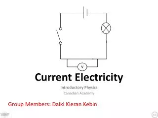
Direct Current Electricity. Modern concepts of electricity. Electric current occurs when there is a flow of charged particles (generally electrons) on a conductor Current flow from positive to negative The reverse direction of actual flow of electrons . Electric current

E N D
Modern concepts of electricity • Electric current occurs when there is a flow of charged particles (generally electrons) on a conductor • Current flow from positive to negative • The reverse direction of actual flow of electrons
Electric current • The flow of charge in a definite direction • Measure of electric current • time rate of flow of charge through any cross section of a conductor • Electric current = Total charge flowing / Time taken • I = q / T • 1 Ampere = 1 Coulomb / 1 sec • Direction of current • Direction of flow of positive charge gives the direction of current (conventional current) • Direction of flow of electrons gives the direction of electronic current • Direction of conventional current is opposite to electronic current
Electric current Factors essential for production of electric current are Potential difference Conducting pathway between the points of potential difference Electrons flow only for as long as the potential difference & pathway exist
Electric potential Condition of a body when compared to neutral potential of earth Unit is: volt Potential gradient Rate of change of potential with respect to distance Directed from an area of low potential to an area of high potential It is a vector quantity W = V/d W- potential gradient V- potential of that point D- distance
Current carriers Charged particles whose flow in a definite direction constitute the electric current are called current carriers Current carriers in solid conductors In solid conductors like metals valence electrons of the atom do not remain attached to individual atoms, but are free to move Under an effect of an external electric field they move in a definite direction causing an electric current Current carriers in liquids In an electrolyte like CuSO4, NaCl etc. there are positively & negatively charged ions These are forced to move in definite direction under the effect of an external electric field Current carriers in gases Gases are insulators of electricity But, can be ionized by applying a high potential difference at low pressures Ionized gas contains positive ions & electrons
Electromotive Force (EMF) Force producing the flow of electrons from more negative to less negative body if similar bodies are charged with different quantities of electricity A volt is that EMF when applied to a conductor with a resistance of one Ohm produces a current of one Ampere Electrons move as so long as potential difference exists between the ends of the pathway
Resistances Obstruction to the flow of electrons in a conductor The unit of electrical resistance is the ohm Cause of resistance Due to the collisions of free electrons with the ions or atoms of the conductor Depends on the arrangement of atoms of the conducting material & length and thickness of conducting wire Resistance directly proportional to the length, temperature inversely proportional to area of cross section & number of free electrons in a unit volume
Factors affecting resistance Material of the conductor Copper for example has a single electron in its outer shell At room temperature kinetic energy of atoms displaces some of these electrons They are free to act as conduction electrons They carry electric charge from one end of conductor to the other 2. Length of the pathway At normal temperatures eve good conductors offer some resistance to electron flow The longer the pathway the greater is the electrical resistance 3. Cross sectional area of the conductor When cross sectional area is greater there is more room for the electrons to pass Therefore resistance is lower If high resistance is required thin wire is used 4. Temperature As temperature increases kinetic movement of molecule increases Increased movement disturbs the passage of electrons So resistance increases
Ohm’s Law The current flowing through a metallic conductor is proportional to the potential difference across its ends, provided that all physical conditions remain constant. If V is potential difference & I is current V = IR R is resistance R = V/I So 1 ohm is defined as The resistance of a body such that 1 volt potential difference across the body results in a current of 1 ampere through it. Limitations of Ohm’s law Temperature of the conductor should remain constant The conducting body should not be deformed It takes place in metallic conductors only
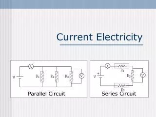
Resistance in Series If components of an electrical circuit are connected in a series there is only one possible pathway for a current as the current has to pass through each resistance, the total resistance equals the sum of individual resistances. If R1, R2 & R3 =resistances V1, V2 & V3 = potential difference From Ohm’s law V1 = IR1 V2 = IR2 V3 – IR3 If potential difference of whole circuit is V V = V1 + V2 + V3 V = IR1 + IR2 + IR3 V = I ( R1+R2+R3) R = R1 + R2 + R3
Resistance in Parallel In this situation the current is offered a number of alternative routs The proportion of current in such resistance depends upon the relative magnitude of the resistances By applying Ohm’s law We can find that the largest resistance carries the smallest current & the smallest resistance carries larges current. 1/R = 1/R1 + 1/R2 + 1/R3
Rheostat A device used to regulate current by altering either the resistance of the current or potential in the part of the circuit It consist of a coil of high resistance wire wound in to an insulating block with each turn insulated from adjacent turns Rheostats have two connections, one to the fixed end of a resistor and the other to a sliding contact on the resistor. Turning the control moves the sliding contact away from or toward the fixed end, increasing or decreasing the resistance. Rheostats control resistance, thus controlling current flow.
Types of rheostat Series rheostat rheostat is wired in series with apparatus If all the wires are included in the circuit resistance is maximum & current is lowest e.g.- in wax bath Shunt rheostat wired across a source of potential difference any other circuit has to be taken parallel to it this apparatus has a current regulating mechanism current is applied directly to patient current intensity can be gradually increased from zero to maximum also known as potentiometer rheostat
Fundamental Electric Charges The least charge found on any body is equal to the charge of electron or proton e = 1.6 X 10⁻¹⁹ coulombs Charge on any body can only be the integral multiple of the charge of electron q = +/- ne n is integer 1,2,3,….
Electric Field Electric field intensity due to group of charges The electric field intensity at any point due to a group of point charges is equal to the vector sum of the electrical field intensities due to individual charges at the same point. E = E1 + E2 + E3……En
Electric Lines of Forces Electric line of force is defined as A path, straight or curved, such that tangent to it at any point gives the direction of electric field intensity at that point. It is the path along which a unit positive charge actually moves in the electrostatic field if free to do so.
Properties of electric lines of forces • Electric lines of forces are discontinuous curves • They start from a positively charged body & end at a negatively charged body • No electric lines of force exist inside a charged body • Tangent to the line of force at any point gives the direction of electric intensity at that point • No two electric lines of force can intersect each other • The electric lines of force are always starting & ending on the conductor. Therefore no component of electric field intensity parallel to surface of conductor
Lines of force due to single positive point charge are directed outwards. The lines of force extend to infinity Force due to single negative point charge are directed radially inwards
When charges are unequal the neutral point is closer to smaller charge
Capacitance Ability of the body to hold an electric charge Its units are farad A farad is the capacity of an object which is charged to a potential of 1 volt by 1 coulomb of electricity At any stage if q is the charge on the conductor & V is the potential of the conductor q ∝ V q = CV C is a constant of proportionality & is called capacity or capacitance of the conductor. Value of C depends on the shape & size of conductor & nature of medium in which capacitance is located.
Factors affecting the capacity of a conductor Area of conductor: it is inversely related to capacity Presence of any conductor nearby: in case, potential decreases, so capacity increases Medium around conductor: the capacity increases when any other medium is placed around the conductor
The capacitor (condenser) A device for storing an electric charge In its simplest form it consists of two metal plates separated by an insulator called the dielectric If the plates are given opposite static electric charges the electric lines of force concentrate between the plate
The electric field between the plates has an effect on the atoms of the dielectric, causing their electron orbits to distort as they are attracted towards the positive plate. Atoms remain in state of tension until the potential difference across the capacitor is removed
Electric field of a capacitor Electric field between the plates of a charged capacitor consist of electric lines of force They tend to take the shortest possible route between plates
Charging & discharging a capacitor Capacitor can be charged using electrostatic induction Static electric charge is allowed to build up on the plates of the capacitor Or By applying a potential difference across the plates from either the mains or the battery A capacitor discharges when the accumulated charge is allowed to flow of the plates If two plates of opposite charges are connected electrons flow from negative to positive plate until the charges are equal
Parallel plate capacitor Most commonly used capacitor Consists of two thin conducting plates of area Held parallel to each other Suitable distance d apart Plates are separated by an insulating medium like air, paper etc.
Spherical capacitor Consists of a hollow conducting sphere Surrounded by another concentric conducting spherical shell
Variable capacitor Consists of two sets of plates interleaving with one another Constructed in such a way that one set of plates can be moved relative to another, varying the surface area of the plates facing each other When all the surfaces of both sets of plates are fully interleaved the capacitance is maximum Found in radio set & short wave diathermy machines Q
Grouping of capacitors Two types Capacitors in series Capacitors in parallel
Capacitors in series A voltage applied across four capacitors in series induce charges of +Q and –Q on plates of each. 1/C = V/Q The potential difference across the row is the sum of potentials across each capacitor Single capacitance C equivalent to three capacitors 1/C = (V1 + V2 + V3 + V4) / Q = V1/Q + V2/Q + V3/Q + V4/Q = 1/C1 + 1/C2 + 1/C3 + 1/C4
Capacitors in parallel If capacitors are in parallel Total charge developed on them is the sum of charges on each of them Q = Q1 + Q2 + Q3 + Q4 C = Q1/V + Q2/V + Q3/V Q4/V C = C1 + C2 + C3 + C4