Download
1 / 32
320 likes | 565 Views
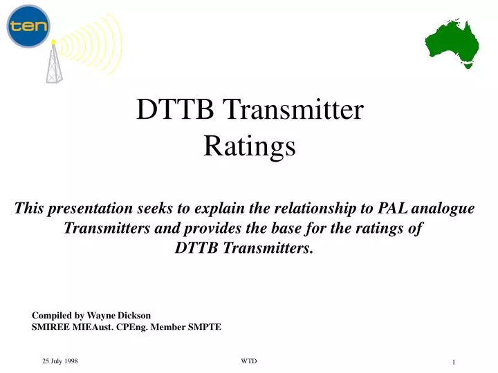
DTTB Transmitter Ratings. This presentation seeks to explain the relationship to PAL analogue Transmitters and provides the base for the ratings of DTTB Transmitters. Compiled by Wayne Dickson SMIREE MIEAust. CPEng. Member SMPTE. DTTB Transmitter Ratings. LINEAR CONSIDERATIONS.

E N D
DTTB TransmitterRatings This presentation seeks to explain the relationship to PAL analogue Transmitters and provides the base for the ratings of DTTB Transmitters. Compiled by Wayne Dickson SMIREE MIEAust. CPEng. Member SMPTE WTD
DTTB TransmitterRatings LINEAR CONSIDERATIONS WTD
COFDMAmplitude Distribution ( CDF = 99.95%) Peak voltage =2.8 (9 dB) - COFDM ( for CDF = 95% peak voltage = 1.7 (4.7dB) ) ( “CDF” - Cumultive Distribution Function ) RMS voltage = 1 (0dB) 9 dB peak to average DIGITAL TV WTD
DTTB Peak Amplitude Distribution (Expanded) 99.95 % CDF WTD
PAL-DTTB Relative Levels Relative Power Levels for PAL/DTTB Ratio = - 6 dB (in dB) Peak 3dB Peak (Peak Sync.) 0dB Average Power 9 dB (Black + Sync.) (if continuous) -2.15dB 6 dB 0 dB Average Power COFDM Difference Analogue PAL DTTB WTD
PAL-DTTB Relative Levels Relative Power Levels for PAL/DTTB Ratio = - 6 dB (in KW) Peak (Instantaneous) Peak (Instantaneous) 20KW 20KW (Peak Sync.) Average Power 10KW 9 dB (Black + Sync.) (if continuous) 6KW 6 dB Average Power 2.5KW 0 dB COFDM Difference Analogue PAL DTTB WTD
DTTB Ratingof a PAL Transmitter • To handle a COFDM signal with a 9 dB peak to average character, a PAL transmitter needs to be derated by : • 6 dB • That is, a 10 KW peak sync transmitter is capable of 2.5 KW COFDM power. • Provided linearity is adequate. • and other parameters are adequate such as : • amplitude and group delay response • LO phase noise • noise level WTD
DTTB TransmitterRatings NON - LINEAR CONSIDERATIONS WTD
DTTB TransmitterNon - linear considerations • The non - linear performance is shown by the intermodulation character displayed in the transmitted spectrum. • The required intermodulation performance is influenced by the multipath performance of the consumer’s receivers. • The performance of a receiver is influenced by the modulation type eg : • whether 64QAM, 16QAM or QPSK • and whether FEC is 7/8, 5/6, 3/4, 2/3, or 1/2 WTD
DTTB Receiver Multipath Performance • An example of a receiver’s performance operating with modulation of 64QAM and a FEC of 2/3 follows. Differences will occur from : • other receiver implementations • complex static multipath • dynamic multipath eg flutter • impulse noise WTD
DTTB System Multipath Performance (Conditions: Static simple multipath, No Co-channel or impulse interference) Outdoor Antennas Indoor Antennas 35 COFDM (64QAM,2/3,1/8) (Nov. 1997) COFDM Picture 25 C/N Threshold (dB) (above curve) Current implementations (April 1998) 19 No Picture (Below curve) 15 0 3 30 Multipath Level ( - dB) WTD W.T.Dickson 16 April 98
DTTB System Multipath Performance under typical reception conditions Indoor Antennas Outdoor Antennas 35 COFDM (64QAM,2/3,1/8) Complex multipath (approximate median) Picture 25 (above curve) C/N Threshold (dB) 19 No Picture Simple multipath (Below curve) 15 0 3 30 Multipath Level ( - dB) WTD W.T.Dickson 16 April 98
DTTB COFDMDecoder Threshold C/N WTD W.T.Dickson 16 April 98
DTTB TransmitterPerformance requirements • By knowing the worse threshold C/N required by the receiver, the required transmission C/N may be derived. • The transmission C/N will be determined by the combination of : • the noise floor at the transmitted power level • the intermodulation at the transmitted power level WTD
DTTB TransmissionC/N requirements • By observing the previous examples, of a receiver operating in a typical to a worse reception condition, the required C/N by the receiver is varies from approximately 20 dB to 35 dB. • Hence the transmitted C/N has to be such that the reception conditions determine the decoding performance, not the transmission conditions. • The following plot will be used to derive the required transmission C/N requirements. WTD
Transmitter C/N interactionwith decoder threshold C/N Hence transmission C/N should be more than 6 dB below decoder C/N for less than 1 dB degrading of decoder C/N 0.2dB influence results from a 13dB difference. WTD
The required DTTB Transmitter C/N • Considering : • (A) @ 35dB required decode C/N, an influence of 1dB by the Transmitted C/N is acceptable. (as such high C/N will not be common the high 1dB influence maybe acceptable) • (B) @ 25dB required decode C/N, an influence of 0.2dB by the Transmitted C/N is acceptable.(as a 25dB decoder C/N requirement will be potentially common a small influence is demanded) • The Transmitted C/N needs to be : • for (A) 41dB for (B) 38dB • Hence 41dB Transmitted C/N appears to be indicated. WTD
Transmitter C/NversusSpectrum regrowth • Although the spectrum regrowth is a reflection of what is occurring within the band of data, there is a 1 to 2dB higher level of “N” within the data area. Hence the regrowth level should be allowed to be 2dB higher than the required Transmitted C/N. • Aim for a Transmitted C/N of 43 dB. • A Transmission C/N of 22 dB is likely to ensure failure of all decoders ! • These requirements are for 64QAM @ FEC of 2/3. WTD
DTTB TransmissionSpectrum Spectrum regrowth level Transmission C/N COFDM Intermod. Commonly called : “spectrum regrowth” or “spectrum spread”. Noise Notes : 1. Intermod. level increases at double the rate the input level is increasing. 2. Noise level increases at the same rate the input level is increasing. 3. As COFDM is the same as noise, the display of C/N is independent of the resolution B/W. 4. The shape of the sidebands is influenced by the transmitter’s response. 5. Either noise or intermod. may dominate. WTD
DTTB TransmissionImplementations • Spectrum “regrowth” or “spectrum spread” is a mirror into what is happening within the modulated spectrum. • Although filtering of the spectrum spread is required for the control of adjacent channel interference, such filtering does not change the the level of intermodulation or noise. • Implementations must ensure that under conditions of maintenance or partial failure that the maximum allowable Transmission C/N of 43 dB is not exceeded. WTD
COFDM - PALSpectrum Analyser Display Spectrum Analyser display : Vision Carrier Dependent upon Resolution B/W setting. Sound Carriers A Chroma eg. If Res. B/W = 300KHz “A”= D + 10Log (6.6 / 0.3) = 23.5 dB DTTB (COFDM) PAL D = DTTB to PAL ratio ( eg D = 10 dB ) Note : It is usually less than this value as resolution B/W shape collects more power than the ideal rectangular filter. When Res. B/W approaches or is less than the separation between the carriers of COFDM : A = D + 10Log (No. of Carriers) DTTB power = average heating power PAL power = the equivalent CW power of peak sync Vision Carrier power WTD
DTTB TransmissionSpectrum Mask Requirements PAL ADJACENT CHANNEL CONSIDERATIONS WTD
DTTB to PALAdjacent Channel requirements • DTTB power and out of band levels will impact upon the interference into the PAL lower and upper adjacent channels. • The required Transmission C/N of 43 dB for proper operation of DTTB will provide some inherent protection of the PAL service if it is guaranteed. • Deduction from the plot following provides some worse case figures. WTD
DTTB to PALInterference Vision (3 dB) Sound (8 dB) Co-channel (45 dB) SCM40 Avg SCM40 Max LOP-10 dB Protection Ratio D/U (dB) DTTB Frequency Offset (MHz) WTD
DTTB Power Levels • Without considering spectrum spread from the DTTB, the power which may exist between DTTB and PAL without causing interference is : • for adjacent channel operation • limited by sound in lower adjacent, DTTB 8 dB below PAL • limited by vision in upper adjacent, DTTB 3 dB below PAL • for co - channel operation • limited by vision, DTTB 45 dB below PAL WTD
DTTB Power Levels • Allowing for a variation of +/- 2 dB in the DTTB to PAL ratio (>4 Km from the two tower transmissions in Sydney), and combining with the previous -8 dB restriction, a -10 dBDTTB to PAL ratio can be allowed without interference into PAL. • This is cautious worse case analysis with the information currently available. • Note that the sound of the lower channel is the restricting criteria. If the vision was the limiting factor a -5 dB DTTB to PAL ratio could be allowed. WTD
DTTB Side Bands • The side bands generated from the spectrum spread or regrowth (from noise or intermod.) may be limited by the “Co - channel” restrictions imposed upon the DTTB to PAL ratio. • As shown the co - channel DTTB to PAL ratio without causing interference is - 45 dB.(flat spectrum across PAL) • As the side bands only need to be down this far, the DTTB to PAL ratio can be deducted from this figure to arrive at the Transmission C/N which will produce PAL interference. • Hence with a DTTB to PAL ratio of 10 dB, the side band level may be - 35 dB. ( ie 35 dB Transmission C/N) • Hence the side band levels are controlled by the DTTB decoding requirements of 43 dB Transmission C/N. WTD
Braodcast Spectrum Vision Carrier (peak sync) DTTB to PAL eg -10 dB 0 dB Carrier only no modulation Sound Carriers -13 dB Chroma -20 dB DTTB COFDM PAL (Lower) PAL (Upper) WTD
DTTB SpectrumMask Base • Based upon DCA Comms. Laboratory subjective testing using the SCM40 method for vision interference levels and a deduction from the LOP method for sound interference levels. • Adjacent channel operation with matching coverage patterns of DTTB and PAL, transmitted from the same area. • DTTB to PAL ratio of -10 dB required for adjacent channel protection of PAL from DTTB. • The DTTB side bands are required to be 45 dB below PAL vision to protect PAL. • The mask is conservative allowing for the introduction of DTTB into a 100 % PAL market. WTD
DTTB SpectrumMask P- 42 dBm/4KHz (P-10-10LogB/W) @ D = - 10 dB & P = 10 KW -3.5 MHz +3.5 MHz 28 dBm/4KHz 43 dB * Intermod. P- 77 dBm/4KHz (P-10LogB/W- 45 dB) - 7 dBm/4KHz 10.5 MHz -10.5 MHz (- 15 dBm/4KHz) * dependent upon modulation parameters D = DTTB to PAL ratio(DTTB average power to equivalent peak sync average power) = - 10 dB B/W = -1dB Bandwidth of COFDM = 6.6 MHz P = 10 KW (70 dBm) WTD
DTTB SpectrumMask PAL “peak sync” vision carrier power DTTB “single” carrier power Spectral Density (dB/4 kHz) Frequency relative to centre of DTTB channel (MHz) WTD