Download
1 / 11
110 likes | 239 Views
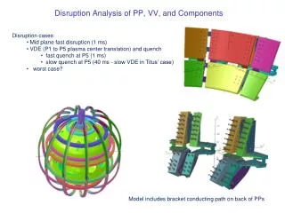
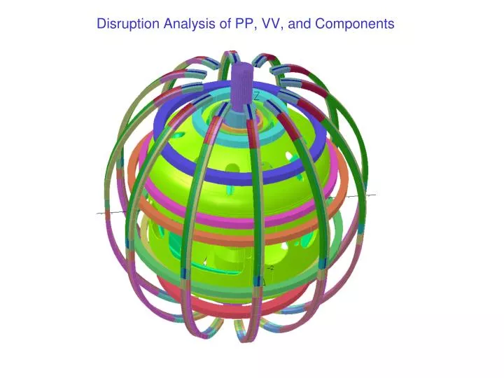
Disruption Analysis of PP, VV, and Components. Opera 3D Model – Transient ELEKTRA Solver. Square shape plasma (same cross section area as circular shape). Fast mid-plane centered disruption 2 MA/ms Back ground field OH, TF and PF coils (#79). Eddy Current Centered Disruption – 60 Degree Model.

E N D
Opera 3D Model – Transient ELEKTRA Solver Square shape plasma (same cross section area as circular shape) Fast mid-plane centered disruption 2 MA/ms Back ground field OH, TF and PF coils (#79)
Eddy Current Centered Disruption – 60 Degree Model Electrical conductivity With gap between PPs – at end of disruption
Eddy Current Centered Disruption – 60 Degree Model 1-2” air gap between plates Gap filled with weld between plates
Eddy Current Centered Disruption – 60 Degree Model Eddy current at end of disruption
Disruption Analysis of PPs Comparison of total induced current (%) • 3D Opera model with square shape plasma (same J as circular shape) • Background field from OH, TF, PF coils • Centered mid-plane disruption • Fast disruption (2 MA/ms) • Eddy current in PPs, VV, CS-Casing • Results 1-2” air gap between PPs Gap filled with SS (change loops in PPs)
Eddy Current Distribution on PP during Mid-Plane Disruption Copper plates Air gap
Eddy Current Distribution on PP during Mid-Plane Disruption Copper plates gap filled with SS
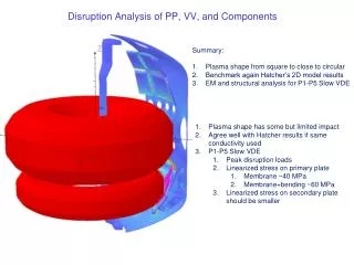
Disruption Analysis of PP, VV, and Components • Discussion • Max background field • Vector potential from 2D continuous model (no gaps between PP) • Induced current from 2D model should in same direction? • Recommendation • Design electrical conducting path to reduce eddy current gradient in PPs to reduced eddies induced bending effect Comparison of peak current density
Disruption Analysis of PP, VV, and Components • Opera Model – R. Hatcher • Max background field from PF and OH coils; no TF coils • Mesh in radial direction to capture skin effect (skin depth?) • Electrical conductivity • Passive plates • VV and CS casing – from measurement (SS?) • Time varying vector potential solution (r*A? electrical scalar potential?) • Opera Vector Potential input to 3D ANSYS model – P. Titus • ELEKTRA combination of total and reduced vector potentials • Total vector potential • Reduced vector potential • Electrical scalar potential
Disruption Analysis of PP, VV, and Components • Recommendation • Design electrical conducting path to reduce eddy current gradient in PPs to reduced eddy induced bending effect?