Download
1 / 32
320 likes | 563 Views
iHome Automation System. Home Automation System Team: Million Dollar Contingency Regiment Adam Doehling Chris Manning Ryan Patterson. Updated Overview:.

E N D
iHome Automation System Home Automation System Team: Million Dollar ContingencyRegiment Adam Doehling Chris Manning Ryan Patterson
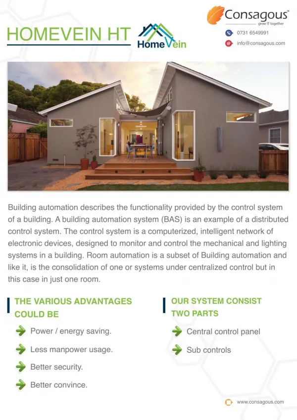
Updated Overview: • The goal of this project is to develop a home automation system that gives the user complete control over all remotely controllable aspects of his or her home. • The automation system will have the ability to be controlled from a central host PC, the Internet, and also remotely accessed via a Pocket PC with a Windows Mobile based application. • We do not have any ‘tangible’ test results to present in this presentation, but we will demonstrate some software we have developed. iHome Security & Automation System
iHome Security & Automation System iHome Automation Overall Flowchart (Review)
Hardware Description-Base Station iHome Control Center USB Base Station RS-485 Wireless L1 Nodes Base Station Block Diagram iHome Security & Automation System
Base Attaches to PC, interfaces between software and hardware. iHome Security & Automation System
Hardware Description-Level 1 Nodes • Controls L0 nodes, replaces light switch, has simple user interface. Level 1 Node L1 Node RS-485 Bus Quadrature Encoders RS-485 Transceiver MCU TI MSP430F149 8-bit Parallel Bus SPI Bus PWM 1 Mb Flash Touch Sensors DigitalPotentiometer LCD Display iHome Security & Automation System
L1 MCU iHome Security & Automation System
L1 comm iHome Security & Automation System
L1 sensor iHome Security & Automation System
L1 touch iHome Security & Automation System
USB programmer iHome Security & Automation System
Hardware Description-Level 0 Nodes • Basic ‘cells,’ controlled by level 1 nodes. Mainly On/Off/Sensor functionality. Since L0 nodes are so varying in what kinds of functions they carry out, it is impossible to block diagram every variety, since they all contain different hardware. Generically, however, they look like this: Level 0 Block Diagram Level 1 Node See next slide for comprehensive list of interface connections Level 0 Node Sensor/Switch iHome Security & Automation System
L1 Device Interface • All L0 Nodes connect to the system via L1 nodes using the following L1 ports: • Eight TTL Output Ports (5V) • Four TTL Input Ports (5V) • Three Analog Input Ports (3.3V) • Four PWM Output Port (5V, resolution of 33,300) • 127 Channel I2C Port (3.6V) • Two SPI Ports (3.6V, 1mbps) • One digital quadrature encoder input (5V) iHome Security & Automation System
RCA/Stereo Mini Connector (30 Ω) 2x22W Speaker Output (4Ω) Stereo Mini Connector Line In Stereo Output MP3/WAV Encoder/Decoder VLSI1003 SPI 8-bit Parallel Addressed Bus 8-bit parallel bus with latched/ translated address bus MCU Atmel AT91SAM7S256 (ARM7TDMI Core) Ethernet Realtek 8019AS 512kbyte SRAM Buffer CY62148BLL L2 Block Diagram RJ45 Connector Hardware Description-Level 2 Nodes • Controls audio communications, no user interface iHome Security & Automation System
L2 mcu iHome Security & Automation System
L2 ether iHome Security & Automation System
L2 audio iHome Security & Automation System
L2 power iHome Security & Automation System
Hardware Description-Level 3 Nodes • Level 3 node portion of the project has been cancelled due to unexpected budget cuts. • Level 3 nodes were intended for streaming video between the central server, TVs, and video cameras. This would require expensive hardware that is now not able to be purchased or developed. iHome Security & Automation System
Software Overview Recall: • There are three main software applications in this project: The iHome Control Center, the Remote Control Center, and the Webserver Webserver Remote Control Center iHome Control Center iHome Security & Automation System
iHome Control Center Low Level Node ‘Pairing’ Map New Node Information Request Command for L2 Node (direct user call or Timed system call) Low Level Node ‘Pairing’ firmware adjustment Low Level Node Command Software: iHome Control Center Block Diagram Output (Webserver DLL): User Input (via GUI): Command Web Server Timed Event Basestation (From Web Server) iHome Security & Automation System
Command Confirmation Node addition or pairing Command Confirmation Info request Software: Web Server Block Diagram iHome Control Center Output (via Windows Messaging): Input (from iHome CC) Information Request Command Command Confirmation Web Server (via TCP/IP Wireless comm) Remote Control Center Information (nodes, rooms) (from remote CC) Command (from web user) (via http comm) Command Web User Timed Command iHome Security & Automation System
Information Request Command Information Request (node, state, rooms) Confirmation of Instruction Software: Remote Control Center Block Diagram Output (via TCP/IP wireless comm.): User Input (via GUI): Remote Control Center Command Web Server GUI iHome Security & Automation System
Or, Generally: Nodes iHome Control Center Web Server Remote Control Center Web User iHome Security & Automation System
Progress made this semester: -What has been done? • Hardware • Design of L0 device for dimming incandescent light bulbs • Partial Design for wireless USB base station • USB L0 device programmer completed • Firmware/Software • Ability to do firmware upgrades of L1 Nodes remotely implemented • GUI of iHome Control Center • Webserver interface with iHome control center • User interface for webserver • GUI for Pocket PC application • Miscellaneous: • Construction of roomish structure started iHome Security & Automation System
Updated Objectives for This Semester -What needs to be done? • Hardware • Design a wired & wireless USB Base Station • L0 nodes for physical control of systems • Completion of construction of higher-order nodes • Firmware/Software • Completion of GUI and code for both the central server (iHome Control Center) and the remote user (Pocket PC) interface • Completion of firmware for the L1 – L2 nodes • Completion of all firmware for the Base Station • Webserver for both remote access and L2 node communication iHome Security & Automation System
Updated Division of Labor -Who is doing what? • Adam- completion of web server, and L0 node completion, and completion of L2 node design / programming. • Chris- user interface for Pocket PC, completion of various peripheral hardware. • Ryan- completion of the iHome Control Center, and completion of L0 nodes, L1 nodes, and USB Base Station. iHome Security & Automation System
Updated Schedule -When will everything be done? • Milestone 1- • Schematics for Base station, wireless adapters for L1 nodes, and light dimmer L0 node completed; PCB layout underway. • Remote firmware update ability implemented. • Communications handler for iHome Control Center completed • Remote Control Center basically functional • TCP/IP communications for L2 nodes completed • Framing of roomish structure completed iHome Security & Automation System
Updated Schedule -When will everything be done? • Milestone 2- • All circuit boards assembled and tested • Device pairing finished and scheduler underway for iHome Control Center • Roomish structure sheetrocked, mudded, and texturized • Remote Control Center completed • L2 Nodes completed • L1 Nodes installed in roomish structure iHome Security & Automation System
Updated Schedule -When will everything be done? • Expo- • Webserver finished • L1 Nodes successfully controlling lights and outlets • Roomish structure painted • Users Manual completed • All software completed • Adam, Ryan and Chris’ software communicating seamlessly with one another iHome Security & Automation System
Demo! iHome Security & Automation System
? iHome Security & Automation System