Download
1 / 39
390 likes | 400 Views
Chapter 2 (handout 1– only sections 2.1, 2.2 and 2.3). 1 of 10. Dr. Clincy Professor of CS. Tough Day: (1) Multiple lectures, (2) Exam covering Ch 4 and 5.1 and 5.2, (3) Lab after exam. OSI Reference Model.

E N D
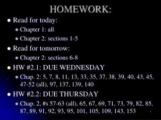
Chapter 2 (handout 1– only sections 2.1, 2.2 and 2.3) 1 of 10 Dr. Clincy Professor of CS Tough Day: (1) Multiple lectures, (2) Exam covering Ch 4 and 5.1 and 5.2, (3) Lab after exam Lecture
OSI Reference Model • The data communications part of the course will be structured around the OSI reference model • We will focus on the bottom layer – similar to computer architecture (physical) • The remaining layers will be covered in CS3550 (new course) and CS4500 (advanced course in TCP/IP) Lecture
Why Study OSI? OSI Reference Model • An excellent model for conceptualizing and understanding data communications • More granularity in functionality - more functional delineation • Key points: • Modular • Hierarchical (chain of command, pecking order) • Boundaries between layers (called interfaces) NOTE: the protocols or functionality with in the layer could change however, the interface remains the same – this facilitates the flexibility Lecture
Advantages of Layering • Easier application development • Network can change without all programs being modified • Breaks complex tasks into subtasks • Each layer handles a specific subset of tasks • Communication occurs • between different layers on the same node or stack (INTERFACES) • between similar layers on different nodes or stacks (PEER-TO-PEER PROCESSES) Lecture
Top Layer Top Layer Some Intermediate Layer Some Intermediate Layer Bottom Layer Bottom Layer OSI’s Layered Approach Example Network A Network B Actual commands invoked, presentation Facilitate the actual communications Network interfaces, raw bits How does peer-to-peer communication work ? Lecture
Open Systems Interconnection Developed by ISO (International Organization for Standardization) Contains seven layers Application Presentation Session Transport Network Data Link Physical OSI Lecture
OSI’s Layered Approach • between different layers on the same node or stack (INTERFACE) • between similar layers on different nodes or stacks (PEER-TO-PEER PROCESSES) Lecture
OSI Reference Model ? • Bottom 3 layers • Responsible for getting data or info to destination • Routing and switching occurs • Define the electrical and physical standards • Performs bit ordering, transmission of the bits, and error detecting and correcting • Top 4 layers • Creation and interpretation of the data • Protocols for data formatting, message syntax, dialogue management, message sequences and info presentation are used Lecture
OSI Physical Layer • Responsible for transmission of bits • Always implemented through hardware • Encompasses mechanical, electrical, and functional interfaces • Encoding and Decoding issues: how 0’s and 1’s are converted to signals • Signal translation (ie. electrical to optical) • Signal Multiplexing and Demultiplexing • Signal Modulation and Demodulation • Transport medium: Coaxial, Twisted Pair, Optical, etc.. • Transmission Rate/Data Rate – how fast to send bits • Transmission mode: transmission direction (simplex, duplex) • Physical Topology: network layout Lecture
Actually sends the packets (groups of frames) from node to node using a routing algorithm Network Layer Data Link Layer Takes raw data (bits) and transform them into frames, error control, etc. Transmit and receive the raw data (bits) Physical Layer OSI Data Link Layer • Responsible for error-free, reliable transmission of data • Framing, Flow control, Error control (detection/correction), Access Methods • Makes use of physical address because with in the same network Lecture
OSI Network Layer • Responsible for routing of messages through networks • Concerned with type of switching used (circuit v. packet) • Handles routing among different networks • NOTE: with in the same network, only the DATA LINK layer is needed – amongst multiple networks, the NETWORK LAYER is needed • No need for routing with in the same network (LAN) • Routing across “internetworks” • Makes use of logical address vs physical address because not with in the same network Lecture
OSI Network Layer Lecture
Chapter 2 (handout 1– only sections 2.1, 2.2 and 2.3) Dr. Clincy Professor of CS 2 of 10 Lecture
Already covered bottom 3 layers Application Presentation Session Transport Network Data Link Physical Recap - OSI Lecture
OSI Upper Layers • Application • Presentation • Session • Transport • Peer-to-Peer Processes ….. • End-to-End nodes only Lecture
OSI Transport Layer • Isolates messages from lower and upper layers • Breaks down message size (segmentation) (down) and performs re-assembly (up) • Monitors quality of communications channel (oversee all hops) • Selects most efficient communication service necessary for a given transmission (could change over hops) • Flow and Error control for Source and Sink Lecture
OSI Session Layer • Establishes logical connections between systems (up/down) • Manages log-ons, password exchange, log-offs (up/down) • Terminates connection at end of session (up/down) Lecture
OSI Presentation Layer • Provides format and code conversion services • Examples • File conversion from ASCII to EBDIC • Invoking character sequences to generate bold, italics, etc on a printer • The source and sink could operate using different encoding schemes – the presentation layer makes the translations • Security • Compression Lecture
OSI Application Layer • Provides access to network for end-user (end-user being a human being or software application) • User’s capabilities are determined by what items are available on this layer (ie. remote log-in, file transfer, email service, directory service, etc.) Lecture
Recap: What happens at the Intermediate Nodes ? Rx Tx 7 Intermediate Nodes 3 1 1 B C Q T A Z Lecture
COMPLEXITY TO CONSIDER • Any particular node in an internetwork can be functioning as follows simultaneously: • Tx to other internetwork nodes • Rx from other internetwork nodes • Intermediate node to some other internetwork nodes Lecture
The File Transfer Program issues a command to the Application Layer Application passes it to Presentation, which may reformat, encrypt, encode, compress, passes to Session (adds overhead) Session requests a connection, passes to Transport (adds overhead) Transport breaks file into chunks, adds error-checking and flow-control info, process-to-process, passes to Network (adds overhead) Network selects the data’s route (internetworking), passes to Data Link (adds overhead) Data Link adds error-control and flow-control info, passes to Physical (adds overhead) Physical translates bits to signal and transmits the signal, which includes information added by each layer OSI in Action: Outgoing File Transfer Lecture
Physical receives signal and translates to bits, passes to Data Link Data Link checks for errors and performs flow control on bits, formulates bits into some formation (frames), passes to Network Network verifies routing (if intermediate node, determines next hop), passes to Transport Transport checks for errors and performs flow control on the chunks, reassembles the chunks, passes to Session Session determines if transfer is complete, may end session, passes to Presentation Presentation may reformat, perform conversions, decode, decrypt, decompress, pass to Application layer Application presents results to user (e.g. updates FTP program display) OSI in Action: Incoming File Transfer Lecture
US Postal System Analogy • Illustrate how the US Postal System is very similar to how networking works • Will help students better understand (versus memorize) data comm and networking Upper Layers – creating and interpreting the signal, data or info Lower Layers – getting the signal from one place to the next
Chapter 2 and 3Handout #2 Dr. Clincy Professor of CS 3 of 10 Lecture 2
Data Vs Signal • Fully explain the difference between signaland data before getting into the details Lecture 2
We probably have a good idea about digital and analog signals What about analog and digital data ?? Analog data examples Voice Images Digital data examples Text Digitized voice or images Data vs Signals Lecture 2
Electromagnetic Signals - Time • Electromagnetic signal can be expressed as a function of time or frequency • Function of time • Analog (varies smoothly over time) • Digital (constant level over time, followed by a change to another level) ie. sound ie. bits Lecture 2
Periodic Signal Characteristics If the signal’s pattern repeats over and over, we called these signals Periodic Signals Periodic Signals can be either Analog or Digital Lecture 2
Analog Periodic Signal Case • Amplitude (A): signal value, measured in volts • Frequency (f): repetition rate, cycles per second or Hertz • Period (T): amount of time it takes for one repetition, T=1/f • Phase (f): relative position in time, measured in degrees • General sine wave is written as • S(t) = A sin(2pft + f) Lecture 2
Varying S(t) = A sin(2pft + f) Lecture 2 Note: 45 degrees because p is 180 degrees
What is Wavelength ? • The distance an electromagnetic wave can travel in the amount of time it takes to oscillate through a complete cycle • Wavelength (w) = signal velocity x period or propagation speed x period • Recall: period = 1 / frequency Another perspective of Wavelength: how far did this signal travel AS the signal goes through a FULL cycle ? Lecture 2
Electromagnetic Signals Electromagnetic signal can be expressed as a function of time or frequencyFunction of frequency (more important) Frequency-Domain Plot – peak amplitudes with respect to frequency Time-Domain Plot – amplitude changes with respect to time Different signals Lecture 2
Electromagnetic Signals - Frequency • Electromagnetic signal can be expressed as a function of time or frequency • Function of frequency (more important) • Spectrum (range of frequencies) • Bandwidth (width of the spectrum) When we talk about spectrum, we mean the range of frequencies the electromagnetic signal takes on In the example, the signal has a Frequency range of f to 3f Therefore, a electromagnetic signal can be a collection (addition) of periodic analog Signals (Composite Signal) Lecture 2
Composite Periodic Signal According to FOURIER ANALYSIS, a composite signal is a combination of sine waves with different amplitudes, frequencies and phases. Could converged to a square wave 3rd harmonic 9th harmonic Lecture 2
Electromagnetic Spectrum for Transmission Media Tell them how to study this chart Lecture 2
Digital Signaling • represented by square waves or pulses • Refers to transmission of electromagnetic pulses that represents 1’s and 0’s 1 cycle amplitude (volts) time (sec) frequency (hertz) = cycles per second Lecture 2
Digital Signal Rate • Each bit’s signal has a certain duration • Example, given a data rate of 50 kbps (or 50,000 bps) • Each would have a 0.02 microseconds duration • Duration (or bit length) = 1/50000 = .00002 sec = .02 msec Lecture 2
Digital Signal Sending 1 bit per level Sending 2 bits per level How many levels needed to send 5 bits at a time ???? # bits per level = log2 of (#oflevels) Lecture 2