Download
1 / 59
600 likes | 775 Views
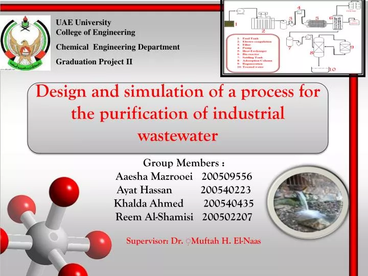
UAE University College of Engineering Chemical Engineering Department Graduation Project II. Design and simulation of a process for the purification of industrial wastewater. Group Members : Aaesha Mazrooei 200509556 Ayat Hassan 200540223 Khalda Ahmed 200540435

E N D
UAE University College of Engineering Chemical Engineering Department Graduation Project II Design and simulation of a process for the purification of industrial wastewater Group Members : AaeshaMazrooei 200509556 AyatHassan 200540223 Khalda Ahmed 200540435 Reem Al-Shamisi 200502207 Supervisor: Dr. ِMuftah H. El-Naas
Outlines Objectives. Introduction. Process Selection. Material and Energy Balance. Equipments Design (Sizing). Alternative Design. Cost Estimation. HAZOP Analysis. Conclusion.
Objectives • A full design of a process for the purification of industrial wastewater which can be applied in the UAE. • An economical analysis of the process including estimation of the manufacturing and operating costs. • An assessment of the ethical, safety and environmental issues related to the process. • a comprehensive HAZOP study on main equipments.
Introduction • Petrochemical and petroleum refinery processes usually generate huge amounts of highly contaminated water that must go through a combination of treatment steps to reduce the concentrations of different contaminants to acceptable discharge levels. • UAE has one of the most stringent environmental regulations, especially those related to discharge limits. • Wastewater is usually treated using different technologies taken into considerations many specifications to be used at the end for discharging to marine environment.
Process Selection • Based on our comparisons and literature review three treatment processes are used which are electro-coagulation, bioreactor and adsorption and the auxiliary units are settling tanks, filters, pumps and heat exchanger.
Selection of auxiliary unit A ) settling tank: • circular: commonly used in municipal and industrial applications. easy sludge removal and high clarification efficiency. used for small to medium sized applications. - Rectangular: usually used for large scale processes. high cost and needs large area.
Material Balance • General Equation: • Electro-Coagulation Unit - The designed process treats 40 of wastewater generated from petroleum refinery with concentrations of contaminants:
Material Balance • B) Bioreactor (BR) Unit:
Material Balance • C) Adsorption (AD) Unit:
Energy Balance around AD ∆H= n Cp ∆T ∆T= 0.89 oC
Design and simulation of a process for the purification of industrial wastewater PFD
Equipments Design (Main Units) A.1)Electro-Coagulation Unit: - Design Criteria :
Equipments Design (Main Units) A.1)Electro-Coagulation Unit: When the flow rate is 40 m3/hr After substituting in the previous equation; D = 3.7 m and H = 7.4 m H = 2D
Equipments Design (Main Units) A.1)Electro-Coagulation Unit: When the flow rate is 13.3 m3/hr
Equipments Design (Main Units) A.2)Electrode Sheets Sizing: Given parameters of electrode sheets:
Equipments Design (Main Units) A.2)Electrode Sheets Sizing: • Where: D1 : electrode diameter • N: number of electrode sheets • Distance: space between electrode sheets • T: thickness of electrode sheets
Equipments Design (Main Units) A.2)Electrode Sheets Sizing: Net working volume = total reactor volume – electrode volume
Equipments Design (Main Units) Final Results: Where as : Energy consumption in (kwh/m3). Power requirement is in (kwh). Current = (current density)(Anode Area) Power = (reactor's volume)(energy consumption) • The supplied voltage for electro-coagulation unit is 480 volts and the current density is assumed to be equal to 10 A/m2.
Equipments Design (Main Units) Final Results:
Equipments Design (Main Units) B) Continuous stirred tank bioreactor sizing: The following equation represents a mole balance on the bioreactor: Parameters entered in polymath to solve the differential equation:
Equipments Design (Main Units) B) Continuous stirred tank bioreactor sizing: • To calculate the working volume and PVA volume the following equations were used assuming that 70% of the bioreactor vessel is the working volume and 30% is the volume of PVA.
Equipments Design (Main Units) C) Adsorption Sizing: • Where, • Vbed: Volume of the bed (m3) • ρbulk: Bulk density of the GAC inside the column (kg/m3)
Equipments Design (Main Units) C) Adsorption Sizing: M(GAC) = 56580.04 Kg • Since there are three AD column in parallel with their regeneration • V = 126/3 = 42 m3
Equipments Design (Main Units) C) Adsorption Sizing: H/D = 4 • D=2.2 m • H=( 4)(2.2)= 8.7 m
Equipments Design (Main Units) C) Adsorption Sizing: H/D = 4 • D=2.2 m • H=( 4)(2.2)= 8.7 m
High rate Sand Filter Design: High rate Sand Filter condition: • The flow rate is 40.85 m3/h for 0.5 hr backwash • L/B = 1.3 • 1.3B2 = 3 • B = 1.5 m; L = 1.5 x 1.3 = 2 m
Pump sizing and power estimation Power is calculated by using the following equation; Power Estimation and Head Pressure Heuristics of pumps (Centrifugal Pumps)
Settling tank Sizing: Two settling tanks will be needed and the design criteria for the settling tanks are shown as the following: • Typical design parameters for primary settling tank Wastewater feed flow rate (Q) was estimated to be 960 m3/day. The typical design parameters for primary settling tank are as follows: Surface settling rate (V) = 49 m3 / (m2 .d) Q = V A ….. A= Q/V=19.6m2 V=d * 4d = 19.6 d = 2.2 m Tank Width = d = 2 m Tank length = 4d = (4) (2) = 8 m Tank depth = 3 m (From table) • Results of settling tank
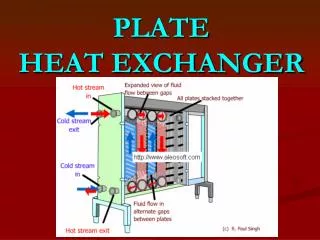
Heat Exchanger Design The heat duty for shell side is equal the heat duty for tube side by using this equation: The equation below was used to calculate the Was found from figure We are dealing with liquid to liquid stream, so that range of U will be from (800-1500) (Watt/m2.°C) To find the number of tube, the value of length was assumed to be 2.6 m because the range of length in heuristics is ( 2.5- 6.5) m, and then by substituting in the equation, the number of tubes will be found
Heat Exchanger Design Tube side calculation Then, for non viscous was determined by using equation: inside heat transfer coefficient was calculated from:
Heat Exchanger Design Shell side calculation (baffle spacing) = 0.2 velocity was determined from this equation
Heat Exchanger Design Trial and error method was used in order to reach the assumption value The nearest answer for assumed overall heat transfer coefficient is the U0 Table ()Results of heat exchange calculation
Comparison of Design Results with Software Packages Manual and Super Pro design comparisons.
Discussion of possible Design Alternatives Comparison between the selected design and alternative design.
Process Economics Capital Cost Estimation: • First of all the cost of the equipments were calculated at ambient pressure and using carbon steel as the material of construction. This cost was calculated as follows:
Process Economics • Pressure drop factor for vessels: • Pressure factor for other equipments:
Process Economics • Bare Module Cost Factor: • Bare Module Cost:
Process Economics • Bare Module Cost Factor: • Bare Module Cost: • Total Bare Module Cost For All Equipments:
CBM and CTM Tables • Total bare module cost at 2001
CBM and CTM Tables Total bare module cost at 2001
CBM and CTM Tables • CTM at 2001: • CTM at 2010:
CBM and CTM Tables • Comparison between Manual Calculation and CAPCOST:
Manufacturing Cost • Cost of Manufacture (COM) = Direct Manufacturing Costs (DMC) + Fixed Manufacturing Costs (FMC) + General Expenses (GE) • Total Direct Manufacturing Cost: DMC = CRM + CWT + CUT + 1.33COL + 0.03COM + 0.069FCI
Manufacturing Cost • Total Fixed Manufacturing Costs: • FMC = 0.708COL + 0.068FCI+ depreciation • Total General Manufacturing Expenses: • GE = 0.177COL + 0.009FCI+ 0.16COM
Manufacturing Cost • Total Cost of Utilities: