Download
1 / 33
330 likes | 466 Views
Chapter 4 Air-Conditioning Components. Standard and Optional Equipment. Compressors. Usually belt driven from the engine Usually have an electromagnetic clutch to turn on/off Two refrigerant lines suction (larger) draws low pressure, low temp vapor from evaporator

E N D
Compressors • Usually belt driven from the engine • Usually have an electromagnetic clutch to turn on/off • Two refrigerant lines • suction (larger) draws low pressure, low temp vapor from evaporator • discharge (smaller) lets out high pressure, high temp vapor to the condenser
Compressor main functions • Raise the pressure of the refrigerant • When compressed the refrigerant temperature rises (no heat is added by the compressor) • Important for proper heat transfer • Create low pressure in the evaporator • Allows refrigerant to vaporize (boil) absorbing large amounts of heat • Circulate refrigerant and oil
Compression stroke forces intake closed and pushes out compressed vapor through exhaust
Compressor Maintenance • Oil level needs to be checked when the system is discharged • Compressor seal replacement • Replace valve plates or gaskets (low psi) • Replace electromagnetic clutch • Belt tension
Rotary Vane Compressor Ford used this compressor at one time.
Centrifugal Force throws vanes outward sealing them against the wall
Variable Displacement Compressor Compressor runs continually, no clutch cycling. A control valve senses evaporator load and automatically changes the displacement to meet the system needs.
Maximum displacement, wobble plate maximum angle (compressor runs continuously)
Minimum displacement, wobble plate minimum angle (compressor runs continuously)
Control valve for Variable Displacement The angle of the swash plate is controlled by the bellows activated control valve, located in the rear of the head, that senses the suction pressure.
Scotch Yoke (R4) opposed pistons Used in GM, notorious for shaft seal failures, and being very noisy.
(Scotch Yoke) Pistons pump by following the contour Suction valve in the piston.
Scroll Compressor(requires very little hp found only on small cars) Not very common yet, very efficient.
Oil Loss • External leak • Refrigerant caries out oil • System recovered in a recovery machine • Measure and reinstall • Component replacement • Oil can be trapped in the old component • Hybrid uses dielectric oil
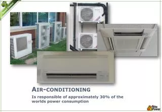
Key points • Heat moves to less warm • Heat transfer quickly with large differences • Fins increase surface area to dissipate heat • Cooling effect causes refrigerant to change states from high psi vapor to high psi subcooled liquid • Must keep clean and fins straight for proper air flow
Receiver-Drier • Liquid refrigerant from the condenser enters • Filters • Removes moisture • Stores excess • Pickup tube ensures that only liquid exits (properly charged system) • Desiccant is hygroscopic (absorbs moisture) • Different for R-12 and 134a • Moisture reacts with refrigerant to form hydrochloric acid.
Drier Location and Mounting • Located in a cool dry place • Desiccant can absorb more moisture when it is less warm • Mounted vertically • Pickup tube in the bottom to only take liquid • Mounted horizontally • JD uses a side pick-up tube • Make sure “top”
Sight Glass R-12A-normal, B-bubbles, C-oil streaking Bubbles usually indicate a loss of refrigerant, streaking usually indicates no refrigerant.