Download
1 / 13
140 likes | 413 Views
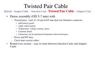
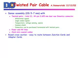
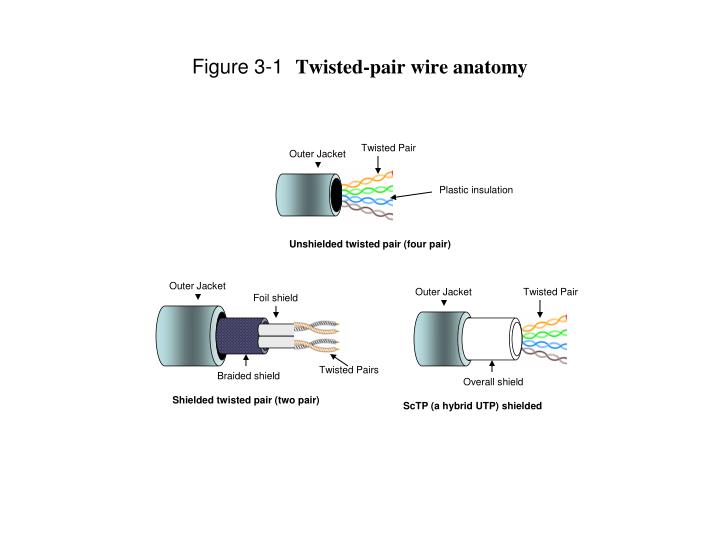
Twisted Pair. Outer Jacket. Plastic insulation. Outer Jacket. Foil shield. Unshielded twisted pair (four pair). Twisted Pairs. Braided shield. Outer Jacket. Twisted Pair. Overall shield. Shielded twisted pair (two pair). ScTP (a hybrid UTP) shielded.

E N D
Twisted Pair Outer Jacket Plastic insulation Outer Jacket Foil shield Unshielded twisted pair (four pair) Twisted Pairs Braided shield Outer Jacket Twisted Pair Overall shield Shielded twisted pair (two pair) ScTP (a hybrid UTP) shielded Figure 3-1Twisted-pair wire anatomy
D C A B Figure 3-2 Coaxial cable anatomy
Single-mode Multimode Multimode Multimode Buffer coating 10 - 125 microns 50 - 125 microns 62.5 - 125 microns 100 - 140 microns Core Cladding Figure 3-3Fiber-optic cable anatomy
Single-Mode Multimode ST Connector SC Connector Figure 3- 4 Single and Multimode Fiber-optical connectors
PBX PBX Business Business Data Data Central Office Central Office Before Bypass PBX PBX Business Business Data Data Central Office Central Office Bypass Figure 3-5 Bypass
Microwave Microwave Business Business LAN LAN Figure 3-6 A LAN interconnect using microwave
GEO 35,900 km MEO 10,400 km MEO LEO 7-1400 km LEO Earth’s Surface Figure 3-7 Satellite Coverage
GEO MEO LEO Figure 3-8LEO, MEO, GEO relative orbit levels
30,000 MHz Satellite Ka Band (19-22 GHz) Satellite KU Band (10.7-12.75 GHz) Satellite C Band (3.4-4.8 GHz) UHF TV Broadcast VHF TV Channels 7-13 (470-884 MHz) FM Radio Broadcast (88-106MHzz) VHF TV Channels (54-82 MHz) CB Radio Channels (27 MHz) AM Radio Broadcast (.5-1.6 MHz) SHF – Super High Frequency UHF – Ultra High Frequency VHF – Very High Frequency MF – Medium Frequency LF – Low Frequency VLF – Very Low Frequency 3000 MHz SHF UHF VHF Short Wave MF LF VLF 300 MHz 30 MHz 3 MHz 300 kHz 30 kHz 3 kHz Figure 3-9The electro-magnetic spectrum
GEO Satellite Host Computer VSAT Terminal VSAT Master Station VSAT Terminal VSAT Terminal VSAT Terminal Earth Station Figure 3-10 A VSAT system
Internet Wireless PCs Cable/DSL Modem ISP (Internet Service Provider) Access Point ATA Wired PCs VoIP Phones Figure 3-11 WiFi anatomy
Internet WiMAX 802.16 Transmitter WiMAX 802.16 Transmitter Line-of-site Back Haul Line-of-site Back Haul ISP Network Non Line-of-site Transmission Customer’s Receiver connects to Router/Access Point inside home. Customer’s Receiver Residence or Business Figure 3-12 WiMAX anatomy
Chapter 03 [FIG] Figure 3-1 Twisted-pair wire anatomy [FIG] Figure 3-2 Coaxial cable anatomy [FIG] Figure 3-3 Fiber-optic cable Anatomy [FIG] Figure 3-4 Single-mode and multimode connectors [FIG] Figure 3-5 Bypass [FIG] Figure 3-6 A LAN interconnection using microwave [FIG] Figure 3-7 Satellite Footprints [FIG] Figure 3-8 LEO, MEO, GEO relative orbit levels [FIG] Figure 3-9 The Electro-Magnetic Spectrum [FIG] Figure 3-10 VSAT system [FIG] Figure 3-11 WiFi anatomy [FIG] Figure 3-12 WiMAX anatomy