Download
1 / 20
200 likes | 209 Views
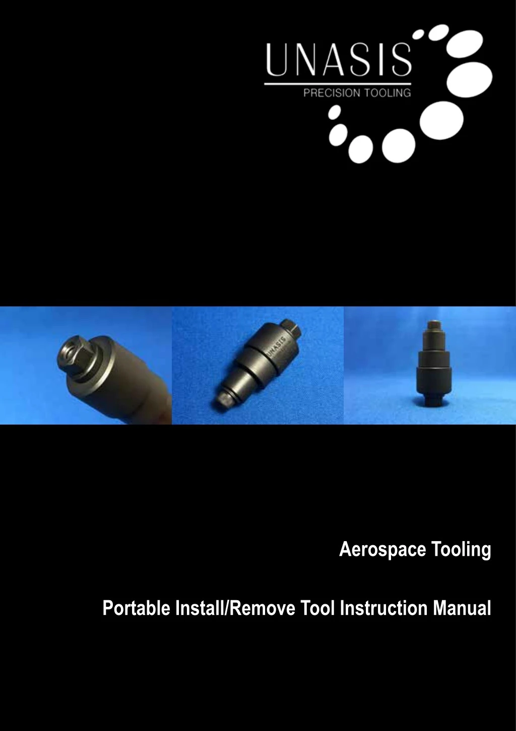
Install removal tools are design to insert and position bearing accurately prior to swaging and to carefully remove the bearing once the swaged lip has been removed. The install / removal tool keeps the bearing perpendicular to the housing ensuring that the housing is not damaged during the installation or removal. If bearings are just pressed into the housing the sharp edges of the bearing could score the housing bore. Care should always be taken when installing or removing bearings. To Know More Visit: http://www.carterbearings.co.uk/aerospace-bearing-tools/<br>

E N D
Aerospace Tooling Portable Install/Remove Tool Instruction Manual
GLOBAL MASTER DISTRIBUTOR: GLOBAL MASTER DISTRIBUTOR: Carter Manufacturing Limited Carter Manufacturing Limited TEL: +44 (0)1865 821 720 EMAIL: sales@carterbearings.co.uk TEL: +44 (0)1865 821 720 EMAIL: sales@carterbearings.co.uk 1 sales@unasisbearings.com www.unasisbearings.com Tel: +44 (0) 1235 527 770 2 sales@unasisbearings.com www.unasisbearings.com Tel: +44 (0) 1235 527 770
Table of Contents Table of Figures ................................................................... 4 Part List ............................................................................... 5 Tool Component Breakdown ................................................ 6 Precautions Prior to Use ...................................................... 7 Install Bearing ...................................................................... 8 Step 1 ............................................................................. 8 Remove receiver cup from tool assembly ................. 8 Unasis Portable Install/Remove Tool Step 2 ............................................................................. 9 Assemble tool on bearing with primary anvil position 9 Step 3 ............................................................................. 10 Tighten tool until bearing touches down on locating anvil ............................................................. 10 Step 4 ............................................................................. 10 Rotate locating anvil to secondary anvil position ...... 10 Step 5 ............................................................................. 11 Tighten tool until bearing touches down on locating anvil .............................................................. 11 Unasis Portable Proof Load Tool Remove Bearing .................................................................. 12 Step 1 ............................................................................. 12 Remove locating anvil from tool assembly ............... 12 Step 2 ............................................................................. 13 Assemble tool on bearing .......................................... 13 Step 3 ............................................................................. 14 Tighten tool until bearing is successfully removed ... 14 CAD Visual Instructions ...................................................... 15 Primary Installation .............................................................. 15 Secondary Installation ......................................................... 15 Unasis Breakaway Torque Tool Remove Bearing .................................................................. 16 3 sales@unasisbearings.com www.unasisbearings.com Tel: +44 (0) 1235 527 770
Table of Figures Figure 1 - Unasis Portable Install/Remove Tool ..................................................................................................................... 3 Figure 2 - Spanner.................................................................................................................................................................. 5 Figure 3 - Hex Key ................................................................................................................................................................. 5 Figure 4 - Spherical plain bearing .......................................................................................................................................... 5 Figure 5 - Tool component breakdown .................................................................................................................................. 6 Figure 6 - Bearing terminology ............................................................................................................................................... 6 Figure 7 - Disassembled Tool ................................................................................................................................................ 8 Figure 8 - Receiver Cup Removed ........................................................................................................................................ 8 Figure 9 - Washer and Pusher Cup installed on Shaft .......................................................................................................... 9 Figure 10 - Anvil Primary Position (Left) and Secondary Position (Right) ............................................................................. 9 Figure 11 - Anvil Placed Into Housing in Primary Position .................................................................................................... 9 Figure 12 - Tool Assembled on Housing ................................................................................................................................ 9 Figure 13 - Assembly Tightened with Hex Key and Spanner ................................................................................................ 10 Figure 14 - Anvil Rotated to Secondary Position ................................................................................................................. 10 Figure 15 - Assembly Tightened to Install Bearing ................................................................................................................ 11 Figure 16 - Installed Bearing in Housing .............................................................................................................................. 11 Figure 17 - Locating Anvil Removed ..................................................................................................................................... 12 Figure 18 - Washer and Pusher Cup installed on Shaft ........................................................................................................ 13 Figure 19 - Pusher Cup Contacting Cut V-Groove ................................................................................................................ 13 Figure 20 - Tool Assembly Finger Tightened ......................................................................................................................... 13 Figure 21 - Bearing Successfully Removed .......................................................................................................................... 14 Figure 22 - Tool Disassembled and Bearing Removed ......................................................................................................... 14 Figure 23 - Primary Installation ............................................................................................................................................. 15 Figure 24 - Secondary Installation.......................................................................................................................................... 15 Figure 25 - Bearing Removal ................................................................................................................................................ 16 4 sales@unasisbearings.com www.unasisbearings.com Tel: +44 (0) 1235 527 770
Part List Figure 1 – Unasis Portable Install/Remove Tool Figure 4 - Spherical Plain Bearing (not included) Figure 2 - Spanner Figure 3 - Hex Key 5 sales@unasisbearings.com www.unasisbearings.com Tel: +44 (0) 1235 527 770
Tool Component Breakdown Tool Component Breakdown Tool Component Breakdown 1. Shaft 2. Washer 3. Pusher Cup 4. Locating Anvil 5. Receiver Cup 6. Flanged Nut Number 1 2 3 4 5 Tool Component Shaft Washer Pusher Cup Locating Anvil Flanged Nut Figure 5 - Tool component breakdown 1. Shaft 2. Washer 3. Pusher Cup 4. Locating Anvil 5. Receiver Cup 6. Flanged Nut Bearing Terminology (Please put in the same table format as the other manuals) Figure # - Tool components breakdown (Please put in the same table format as the other manuals) Bearing Terminology Figure # - Tool components breakdown Bearing Terminology Figure 6 - Bearing terminology Figure # Bearing terminology 6 sales@unasisbearings.com www.unasisbearings.com Tel: +44 (0) 1235 527 770 Figure # Bearing terminology
Precautions Prior to Use Ensure the housing has suitable clearance for test to be performed. Make sure all contact surfaces are clean and lube dry. The bearing to be installed must have never been previously installed. 7 sales@unasisbearings.com www.unasisbearings.com Tel: +44 (0) 1235 527 770
Install Bearing Step 1 – Remove receiver cup from tool assembly Disassemble tool by unscrewing the flanged nut (6). Remove receiver cup (5) from tool assembly and place to the side as this part will not be necessary for installation. Figure 7 - Disassembled Tool Figure 8 - Receiver Cup Removed 8 sales@unasisbearings.com www.unasisbearings.com Tel: +44 (0) 1235 527 770
Step 2 – Assemble tool on bearing with primary anvil position Insert shaft (1) through washer (2) and then through pusher cup (3) with flat side against the washer (2). Place locating anvil (4) in primary anvil position with flanged side into the backside bore, of the housing. Insert shaft assembly through the bearing bore until the pusher cup (3) is flush with bearing and screw flanged nut (6) until the assembly is finger tight. (See Figure 12). Figure 9 - Washer and Pusher Cup installed on Shaft Figure 10 - Anvil Primary Position (Left) and Secondary Position (Right) Figure 11 - Anvil Placed Into Housing in Primary Position Figure 12 - Tool Assembled on Housing 9 sales@unasisbearings.com www.unasisbearings.com Tel: +44 (0) 1235 527 770
Step 3 – Tighten tool until bearing touches down on locating anvil Use spanner and hex key to tighten assembly until the bearing touches down on the locating anvil. Step 4 – Rotate locating anvil to secondary anvil position Unscrew flanged nut (6) and rotate locating anvil to secondary anvil position with flat side flush against the housing and screw flanged nut (6) until assembly is finger tight. Figure 13 - Assembly Tightened with Hex Key and Spanner Figure 14 - Anvil Rotated to Secondary Position 10 sales@unasisbearings.com www.unasisbearings.com Tel: +44 (0) 1235 527 770
Step 5 – Tighten tool until bearing touches down on locating anvil Use spanner and hex key to tighten assembly until the bearing touches down on the locating anvil which completes installation. Unscrew flanged nut (6) and disassemble tool. The bearing is now properly installed and ready to be swaged. Figure 15 - Assembly Tightened to Install Bearing NOTE: REASSEMBLE THE INSTALL/REMOVE TOOL IMMEDIATELY AFTER COMPLETION TO ENSURE NO COMPONENTS ARE MISPLACED. Figure 16 - Installed Bearing in Housing 11 sales@unasisbearings.com www.unasisbearings.com Tel: +44 (0) 1235 527 770
Remove Bearing Remove Bearing NOTE: One side of the bearing should be cut prior to removal. NOTE: ONE SIDE OF THE BEARING SHOULD BE CUT PRIOR TO REMOVAL. Step 1 Remove locating anvil from tool assembly Step 1 – Remove locating anvil from tool assembly Disassemble tool by unscrewing the flanged nut (6). - - Disassemble tool by unscrewing the flanged nut (6). Remove locating anvil (4) from tool assembly and place to the side as this part will not be necessary for removal. Remove locating anvil (4) from tool assembly and place to the side as this part will not be necessary for removal. Figure 17 - Locating Anvil Removed Figure 12 - Locating Anvil Removed 12 sales@unasisbearings.com www.unasisbearings.com Tel: +44 (0) 1235 527 770
Step 2 – Assemble tool on bearing Insert shaft (1) through washer (2) and then through pusher cup (3) with flat side against the washer (2). Place receiver cup (5) on the backside bore of the housing with open side facing the bearing. Insert shaft assembly through bore of the bearing then through the receiver cup (5) and tighten flanged nut (6) until finger tight. (See Figure 20). NOTE: PUSHER CUP SHOULD BE IN CONTACT WITH V-GROOVE OF THE BEARING THAT HAS BEEN PREVIOUSLY CUT. Figure 18 - Washer and Pusher Cup installed on Shaft Figure 19 - Pusher Cup Contacting Cut V-Groove Figure 20 - Tool Assembly Finger Tightened 13 sales@unasisbearings.com www.unasisbearings.com Tel: +44 (0) 1235 527 770
Step 3 – Tighten tool until bearing is successfully removed Use spanner and hex key to tighten assembly until the bearing is successfully removed from housing and the tool pushes through the housing bore. Unscrew flanged nut (6), disassemble tool and remove bearing from receiver cup (5). Your bearing has now been successfully removed from the housing and a new bearing can be installed if required. Figure 21 - Bearing Successfully Removed Figure 22 - Tool Disassembled and Bearing Removed NOTE: REASSEMBLE THE INSTALL/REMOVE TOOL IMMEDIATELY AFTER COMPLETION TO ENSURE NO COMPONENTS ARE MISPLACED. 14 sales@unasisbearings.com www.unasisbearings.com Tel: +44 (0) 1235 527 770
CAD Visual Instructions Primary Installation Figure 23 - Primary Installation Figure 18 - Primary Installation Secondary Installation Secondary Installation Figure 24 - Secondary Installation Figure 19 - Secondary Installation 15 15 sales@unasisbearings.com www.unasisbearings.com Tel: +44 (0) 1235 527 770 sales@unasisbearings.com www.unasisbearings.com Tel: +44 (0) 1235 527 770
Remove Bearing Figure 25 - Bearing Removal 16 sales@unasisbearings.com www.unasisbearings.com Tel: +44 (0) 1235 527 770
Notes 17 sales@unasisbearings.com www.unasisbearings.com Tel: +44 (0) 1235 527 770
Notes 18 sales@unasisbearings.com www.unasisbearings.com Tel: +44 (0) 1235 527 770
This catalogue has been produced with a great amount of care and attention; all data has been checked for its accuracy. However, no liability can be assumed for any incorrect or incomplete data. Due to the constant development and expansion of the product range, we reserve the right to make modifications without prior notice. All rights reserved. Reproduction in whole or in part without authorisation is prohibited. 19 sales@unasisbearings.com www.unasisbearings.com Tel: +44 (0) 1235 527 770
UNASIS INTERNATIONAL LIMITED UNIT 7, ISIS COURT, WYNDYKE FURLONG ABINGDON BUSINESS PARK ABINGDON OXFORDSHIRE OX14 1DZ UNITED KINGDOM TEL: +44 (0)1235 527 770 EMAIL: sales@unasisbearings.com WEBSITE: www.unasisbearings.com