Download
1 / 29
300 likes | 511 Views
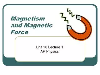
PHY1013S MAGNETIC FORCE. Gregor Leigh gregor.leigh@uct.ac.za. MAGNETIC FORCES. Describe the motion of charged particles in magnetic fields. Calculate the forces and torques exerted on moving charges and current-carrying wires and loops.

E N D
PHY1013SMAGNETIC FORCE Gregor Leighgregor.leigh@uct.ac.za
MAGNETIC FORCES MAGNETIC FORCES • Describe the motion of charged particles in magnetic fields. • Calculate the forces and torques exerted on moving charges and current-carrying wires and loops. • Determine the energy necessary to rotate a magnetic dipole in a uniform magnetic field. • Describe the magnetic properties of materials. Learning outcomes:At the end of this chapter you should be able to…
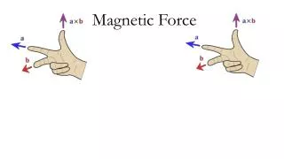
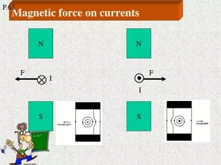
+ + MAGNETIC FORCES MAGNETIC FORCES ON MOVING CHARGES • A positive charge moves at right angles (out of the screen) to a magnetic field… Since it is moving, the positive charge creates its own magnetic field (dotted lines)… The two magnetic fields interact, or superimpose… … giving rise to a magnetic force, , on the moving charge (a force at right angles to both and ).
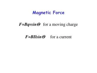
+ MAGNETIC FORCES MAGNETIC FORCES ON MOVING CHARGES • For an electric field: In a magnetic field: Notes: • Magnetism is an interaction between moving charges. (v = 0 no field and/or no force.) • The direction of is given by the RH rule.(A –ve charge experiences in opposite dir’n.) • For = 0°or = 180°,Fmag= 0.For = 90°,Fmag is a maximum: Fmag= qvB. • Since it is always perpendicular to , affects the direction, but not the speedof the charge.
– – + + MAGNETIC FORCES MOTION OF CHARGED PARTICLES IN MAGNETIC FIELDS Case 1: = 0°or 180° Particles continue undeflected.
+ + MAGNETIC FORCES MOTION OF CHARGED PARTICLES IN MAGNETIC FIELDS • The charged particle moves at constant speed in a circle of radius, r. Case 2: = 90° Fmag= qvB isa centripetal force. The particle is describing cyclotron motion. So , from which we derive the cyclotron… …radius: r + …period: …frequency:
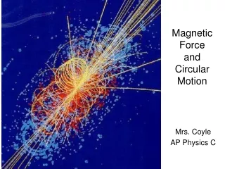
MAGNETIC FORCES THE BUBBLE CHAMBER • Particle physicists used to glean information about elementary particles and the structure of the universe from the tracks left by charged particles passing through super-heated liquid hydrogen in the presence of a magnetic field (perpendicular to the plane of the screen).
MAGNETIC FORCES THE CYCLOTRON • A cyclotron, consisting of two hollow copper “dees”, accelerates charged particles to very high speeds, making use of the fact that the cyclotron period is inde-pendent of particle speed . + – A moderate potential difference between the dees, accelerates a charged particle (e.g. a proton) from one dee to the other…
MAGNETIC FORCES THE CYCLOTRON • As the proton returns to the gap (after exactly ½T), the voltage between the dees is reversed, accelerating the proton into the opposite dee… Shielded from electric fields inside the dee, the proton responds only to the magnetic field, executing a semicircular path at constant speed… – + – + …where once again it travels in a semicircle before returning to the gap for another “kick”.
MAGNETIC FORCES MOTION OF CHARGED PARTICLES IN MAGNETIC FIELDS • The velocity has components both’r and to . Case 3: 0°, 90°, nor180° The charged particle thus describes a helix (a “corkscrew” path) whose axis lies along the magnetic field. p The radius of the helix is determined by v = vsin, while its pitch, p, (the distance travelled along the axis during one rotation) is determined by v= vcosand the cyclotron period, T: p= v T.
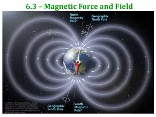
MAGNETIC FORCES THE VAN ALLEN BELTS • A magnetic “bottle” can be produced by using an NON-homogeneous field such that at the “ends” the magnetic force is directed inwards. The Earth’s magnetic field (which converges at the poles) acts in this way, trapping electrons and ions … in the Van Allen radiation belts, and giving rise to the two aurorae. http://500px.com/photo/57402216/beautiful-night-by-jonathan-tucker
+ – MAGNETIC FORCES CROSSED FIELDS: Discovery of the electron • Arranging an electric field and a magnetic field at right angles to each other produces crossed fields. JJ Thomson (1897) used such an arrangement to determine the charge-to-mass ratio (e/m) of the electron: Felec= Fmag y e qE= qvB screen Hence:
2r MAGNETIC FORCES CROSSED FIELDS: The mass spectrometer • A mass spectrometer makes use of their different charge-to-mass ratios to identify the different isotopes in a sample. Atoms are ionised and accelerated before passing through the crossed fields of a velocity selector. – v +q In the filter… Felec= Fmag + i.e. qE= qvB velocity selector/filter m In the dee… m m photographic plate, or CCD Hence:
MAGNETIC FORCES CROSSED FIELDS: The Hall effect • An effect discovered by Edwin Hall in 1879 can be used to determine: • whether the energy carriers in a conductor are positively or negatively charged; • the number of carriers per unit volume of conductor; • the drift speed of the moving charges.
– – – – – + + + + + MAGNETIC FORCES CROSSED FIELDS: The Hall effect (a) • Negative charge accumulates on the left hand edge of the strip until Felec equals Fmag(i.e. equilibrium is established). conventional current,I e– (on –ve carriers as result of charge build-up on strip) I At this point we can measure the Hall voltage, VH, across the strip. If the right hand edge is in fact at a higher potential than the left, the moving charges must indeed be negative.
+ + + + + + – + – – + – + + – MAGNETIC FORCES CROSSED FIELDS: The Hall effect (a) • If the moving charges were positive (as they are in some semiconductor materials)… – – p+ – – e– – I I … the left hand edge of the strip would be at the higher potential and the Hall voltage would be reversed.
t w MAGNETIC FORCES CROSSED FIELDS: The Hall effect (b) • At equilibrium,Felec=Fmag I i.e. eE=evB – + – + – + – + e– Where… A … v is the drift speed, … A is thickness, t, times width, w: A=tw … Hence…
MAGNETIC FORCES CROSSED FIELDS: The Hall effect (c) • By moving the strip mechanically through the magnetic field in the opposite direction to and adjusting the speed of this movement until the Hall voltage drops to I e– I zero, the magnitude of can be determined. (At this speed the speed of the charge carriers relative to the magnetic field must be zero, i.e. the speed of the strip just matches the drift speed of the moving charges.)
MAGNETIC FORCES MAGNETIC FORCES ON CURRENT-CARRYING WIRES • A straight wire, carrying current I in a magnetic field B, will experience a force Fmag (provided the wire makes a non-zero angle with the field). vd I The time taken for the charge carriers in length element to pass any point in the wire is . So the net charge moving through length element during this time is . The force on length of wire is thus: I.e.
I MAGNETIC FORCES MAGNETIC FORCES ON CURRENT-CARRYING WIRES Notes: • ( is defined as a vector of length in the direction of I). • The direction of is given by the RH rule. • For = 0°or = 180°,Fmag= 0.For = 90°,Fmag is a maximum: Fmag= I B. • For a curved wire, we integrate over many infinitesimal straight line segments.
Current in wire 1 creates at every point on wire 2 a magnetic field of strength: FORCE BETWEENTWO PARALLEL CONDUCTORS PHY1013S MAGNETIC FORCES 1 2 d I1 I2 So if there is current in wire 2, it experiences a force due to this magnetic field: F1 on 2= I2B1 I.e. 21
1 2 d I1 I2 MAGNETIC FORCES FORCE BETWEENTWO PARALLEL CONDUCTORS Notes: • F1 on 2and F2 on 1are an action-reaction pair. • Parallel currents attract; antiparallelones repel. • The ampere is defined as that current which, when maintained in each of two parallel conductors of infinite length and situated one metre apart in empty space, causes between them a force of exactly 2 10–7 N per metre of length.
N S MAGNETIC FORCES TORQUE ON A CURRENT LOOP • The forces on the sides perpendicular to the field combine to exert a torque about the central axis. (The forces on the other sides do not contribute to the torque.) I
½b b ½bsin MAGNETIC FORCES TORQUE ON A CURRENT LOOP • Each force in the couple is given byF = IaB, a I I I so the net torque is: (Cf. electric dipole: ) I.e.
MAGNETIC FORCES POTENTIAL ENERGY OF DIPOLES IN FIELDS • Electrical: minimum when= 0° set to zero when= 90° U() maximum when= 180° Magnetic: (Hence the magnetic dipole units: [J/T].)
MAGNETIC FORCES DC MOTOR • The commutator ensures that current always flows in such a way that the left hand side of the coil, or armature, experiences an upwards force, while the right hand side is forced downwards.
MAGNETIC FORCES • The rectangular coil of a moving-coil galvanometer has 36 turns and a resistance of 7 . The effective shaft length of the armature in the magnetic field is 25 mm and the effective width is 20 mm. The magnetic field in the air gap is 0.4 T and the controlling torque of the hairspring is 3.0 Nm per degree of deflection. • Calculate the current required for a full-scale deflection of 90°. • Describe, with the aid of a calculation and a labelled diagram, how the galvanometer must be modified to function as a 0–12 V voltmeter.
MAGNETIC FORCES • N = 36 turns a = 25 10–3 mR = 7 b = 20 10–3 mB = 0.4 T k = 3.0 10–6 Nm/° • Current required for a full-scale deflection of 90°. (a) = NIabBsin For concave poles = 90°: (3.0 10–6)(90) = 36I(2510-3)(2010-3)(0.4) I = 37.5 mA
G G MAGNETIC FORCES • N = 36 turns a = 25 10–3 mR = 7 b = 20 10–3 mB = 0.4 T k = 3.0 10–6 Nm/° • Current required for a full-scale deflection of 90°. • Modification required to function as a 0–12 V voltmeter. V (b) A potential drop of 12 V across Rmeasured must drive a current of 37.5 mA through the voltmeter. multiplier, R RG = 7 I = 37.5 mA V = IR 12 = 0.0375(Rmultiplier + 7) Rmeasured I I.e. Rmultiplier 320 must be connected in series with