Download
1 / 1
10 likes | 161 Views
Engineering design and fabrication of x-band accelerating structures td24 r05 and td24 r05 sic. A. Solodko, A. Samoshkin , D. Gudkov, JINR, Dubna , Russia G. Riddone, A. Grudiev, S. Atieh, CERN, Geneva, Switzerland. Abstract

E N D
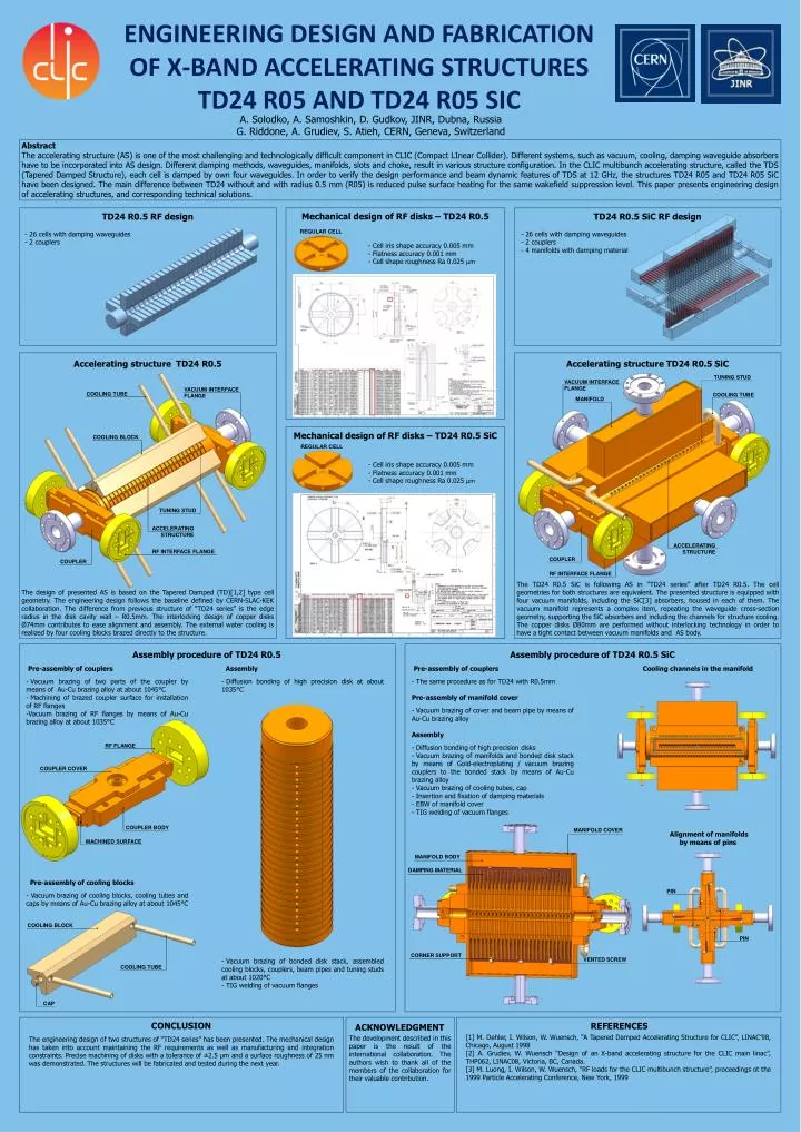
Engineering design and fabrication of x-band accelerating structures td24 r05 and td24 r05 sic A. Solodko, A. Samoshkin, D. Gudkov, JINR, Dubna, Russia G. Riddone, A. Grudiev, S. Atieh, CERN, Geneva, Switzerland Abstract The accelerating structure (AS) is one of the most challenging and technologically difficult component in CLIC (Compact LInear Collider). Different systems, such as vacuum, cooling, damping waveguide absorbers have to be incorporated into AS design. Different damping methods, waveguides, manifolds, slots and choke, result in various structure configuration. In the CLIC multibunch accelerating structure, called the TDS (Tapered Damped Structure), each cell is damped by own four waveguides. In order to verify the design performance and beam dynamic features of TDS at 12 GHz, the structures TD24 R05 and TD24 R05 SiC have been designed. The main difference between TD24 without and with radius 0.5 mm (R05) is reduced pulse surface heating for the same wakefield suppression level. This paper presents engineering design of accelerating structures, and corresponding technical solutions. Mechanical design of RF disks – TD24 R0.5 TD24 R0.5 RF design TD24 R0.5 SiC RF design • 26 cells with damping waveguides • 2 couplers • 26 cells with damping waveguides • 2 couplers • 4 manifolds with damping material REGULAR CELL • Cell iris shape accuracy 0.005 mm • Flatness accuracy 0.001 mm • Cell shape roughness Ra 0.025 μm REGULAR CELL Accelerating structure TD24 R0.5 Accelerating structure TD24 R0.5 SiC TUNING STUD VACUUM INTERFACE FLANGE COOLING TUBE VACUUM INTERFACE FLANGE MANIFOLD COOLING TUBE Mechanical design of RF disks – TD24 R0.5 SiC COOLING BLOCK • Cell iris shape accuracy 0.005 mm • Flatness accuracy 0.001 mm • Cell shape roughness Ra 0.025 μm TUNING STUD ACCELERATING STRUCTURE ACCELERATING STRUCTURE COUPLER RF INTERFACE FLANGE COUPLER RF INTERFACE FLANGE The TD24 R0.5 SiC is following AS in “TD24 series” after TD24 R0.5. The cell geometries for both structures are equivalent. The presented structure is equipped with four vacuum manifolds, including the SiC[3] absorbers, housed in each of them. The vacuum manifold represents a complex item, repeating the waveguide cross-section geometry, supporting the SiC absorbers and including the channels for structure cooling. The copper disks Ø80mm are performed without interlocking technology in order to have a tight contact between vacuum manifolds and AS body. The design of presented AS is based on the Tapered Damped (TD)[1,2] type cell geometry. The engineering design follows the baseline defined by CERN-SLAC-KEK collaboration. The difference from previous structure of “TD24 series" is the edge radius in the disk cavity wall – R0.5mm.The interlocking design of copper disks Ø74mm contributes to ease alignment and assembly.The external water cooling is realized by four cooling blocks brazed directly to the structure. Assembly procedure of TD24 R0.5 Assembly procedure of TD24 R0.5 SiC • Pre-assembly of couplers • Vacuum brazing of two parts of the coupler by means of Au-Cu brazing alloy at about 1045°C • Machining of brazed coupler surface for installation of RF flanges • Vacuum brazing of RF flanges by means of Au-Cu brazing alloy at about 1035°C • Assembly • Diffusion bonding of high precision disk at about 1035°C • Pre-assembly of couplers • The same procedure as for TD24 with R0.5mm • Pre-assembly of manifold cover • Vacuum brazing of cover and beam pipe by means of Au-Cu brazing alloy • Assembly • Diffusion bonding of high precision disks • Vacuum brazing of manifolds and bonded disk stack by means of Gold-electroplating / vacuum brazing couplers to the bonded stack by means of Au-Cu brazing alloy • Vacuum brazing of cooling tubes, cap • Insertion and fixation of damping materials • EBW of manifold cover • TIG welding of vacuum flanges Cooling channels in the manifold RF FLANGE COUPLER COVER MANIFOLD COVER COUPLER BODY Alignment of manifolds by means of pins MANIFOLD BODY MACHINED SURFACE DAMPING MATERIAL Pre-assembly of cooling blocks - Vacuum brazing of cooling blocks, cooling tubes and caps by means of Au-Cu brazing alloy at about 1045°C PIN COOLING BLOCK PIN CORNER SUPPORT VENTED SCREW • Vacuum brazing of bonded disk stack, assembled cooling blocks, couplers, beam pipes and tuning studs at about 1020°C • TIG welding of vacuum flanges COOLING TUBE CAP CONCLUSION REFERENCES ACKNOWLEDGMENT [1] M. Dehler, I. Wilson, W. Wuensch, “A Tapered Damped Accelerating Structure for CLIC”, LINAC’98, Chicago, August 1998 [2] A. Grudiev, W. Wuensch “Design of an X-band accelerating structure for the CLIC main linac”, THP062, LINAC08, Victoria, BC, Canada. [3] M. Luong, I. Wilson, W. Wuensch, “RF loads for the CLIC multibunch structure”, proceedings ot the 1999 Particle Accelerating Conference, New York, 1999 The development described in this paper is the result of the international collaboration. The authors wish to thank all of the members of the collaboration for their valuable contribution. The engineering design of two structures of “TD24 series” has been presented. The mechanical design has taken into account maintaining the RF requirements as well as manufacturing and integration constraints. Precise machining of disks with a tolerance of ±2.5 µm and a surface roughness of 25 nm was demonstrated. The structures will be fabricated and tested during the next year.