Download
1 / 26
270 likes | 378 Views
Low-Cost Current-Fed PMSM Drive System With Sinusoidal Input Currents. 參考文獻 :IEEE TRANSACTIONS ON INDUSTRY APPLICATIONS, VOL. 42, NO. 3, MAY/JUNE 2006 作 者 :Velimir Nedi´c, Member, IEEE, and Thomas A. Lipo, Fellow, IEEE. 指導教授 : 王明賢 報 告 人 : 吳烱華. Agenda.

E N D
Low-Cost Current-Fed PMSM Drive SystemWith Sinusoidal Input Currents 參考文獻:IEEE TRANSACTIONS ON INDUSTRY APPLICATIONS, VOL. 42, NO. 3, MAY/JUNE 2006 作 者:Velimir Nedi´c, Member, IEEE, and Thomas A. Lipo, Fellow, IEEE 指導教授:王明賢 報 告 人:吳烱華
Agenda • I. INTRODUCTION • II. DESCRIPTION OF THE SYSTEM • III. SYSTEM ANALYSIS • IV. SIMULATED AND EXPERIMENTAL RESULTS • V. CONCLUSION
Abstract Standard low- and medium-power drives are basedon thevoltage-source converter topology. There has been lessresearch work on dual topology drives, based on a current-fedinverter structure. Although energy storage is more efficient incapacitors than in inductors, due to some inherent advantagesof current- source converter topology, and at the first place, theabsence of a dc-link electrolytic capacitor, a current-source drivesystem made with a considerably reduced dc link inductor couldbe better low-cost solution with improved reliability, lifetime, and transient response than conventional drive.
INTRODUCTION OVER the last two decades, the traditional voltage-sourceinverter (VSI) topology with a diode rectifier—dc linkcapacitor—pulsewidth- modulator (PWM)-controlled inverterhas become the preferred choice in ac drives for low-cost variablevoltage and frequency power applications [1]. Althoughthis drive system topology employs a simple diode front-end rectifier, it has been found to offer a very favorable performance/cost ratio.
The paper is organized as follows: Section II presents a generaldescription of the new integrated current-fed PMSM drivesystem solution proposed in this paper. A description of the developedrectifier charge-mode controller [9]–[11] and inverterstarting technique are included as well; a system analysis suchas commutation study and power- factor optimization are describedin Section III; Section IV presents the simulated results obtained by using circuit simulator SABER and experimentaldata measured on the laboratory prototype. The description andthe corresponding comments of the starting and steady-stateoperations of the drive system are given in this section.
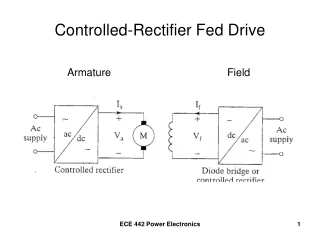
DESCRIPTION OF THE SYSTEM A. Power Circuit Configuration The main function of the PWM rectifier is to regulate thelevel of the dc-link current and to provide sinusoidal currentsat the input of the drive system. A small LC input filtereasily absorbs the high-frequency harmonics injected into theac mains by the rectifier switching action. It should be notedthat although dc-link current contains a harmonic component atsix times the inverter frequency, the rectifier controller enablessinusoidal modulation of the input currents.
The adopted control system configuration is depicted inFig. 1. It is similar to standard control scheme for Synchronousmachine drives, but it employs only a speed controlloop because current control is already included in the rectifier charge controller. It should be noted that motor speedsensing is not necessary because the speed feedback signalcan be derived from the inverter synchronization signals. Thecomplete control system uses only one sensor for the dc linkcurrent. Inverter triggering signals are synchronized to the rotorposition by simple terminal voltage sensing instead of usingposition detectors. Therefore, an additional lowering of cost isachieved by implementing a position sensorless drive system,and, in addition, the machine power factor can be preciselycontrolled.
B. Charge Control of the Three-Switch PWM Rectifier The three-phase step-down rectifier operation is based onthe fact that the dc link inductor current is switched betweenthe input phases such that the equivalent area per switchingcycle reconstitutes a sine-wave current on that phase in thelower part of its harmonic spectrum. Therefore, to sinusoidallyshape converter input currents, it is sufficient that they followa given set of current references in an open-loop fashion. Thebest way to do this is to enable the average value of the inputcurrent vectors to track its corresponding sinusoidal reference. Inasmuch as charge-mode control behaves as an instantaneouslarge-signal average current control of switching converters,it is therefore very suitable for average value control of abuck rectifier.
The adopted modulation scheme is a six-step discontinuousalgorithm, which resembles the natural operation of the threephasebuck rectifier, offers minimum switching action, and issimple to realize. According to this technique, a line cycle isdivided into six sectors, each of 60◦, as shown in Fig. 2.
C. Inverter Starting Scheme At startup and at low speeds, some type of forced commutationis required to commutate the inverter to start andaccelerate the motor until the machine terminal voltages aresufficiently large to ensure reliable commutation. The forcedcurrent commutation between inverter thyristors without anyadditional power circuit components can be accomplished by periodically interrupting the dc-link current. That is, the dc linkcurrent is forced to become zero prior to each commutation byproper gating of the PWM rectifier, thus providing the turn-offof outgoing thyristors. When the dc link current drops to zero,commutation of the thyristor in the inverter bridge is enabled.Natural commutations begin when machine reaches speed atwhich induced back EMFs are large enough to ensure safecommutation.
D. Low-Cost Issues The inspiration to use load-commutated thyristor inverter fordriving PMSM comes from the low-cost requirements of thetarget applications. Almost all of the applications, such as Highvoltageac (HVAC) drives, home appliances, fans, pumps, etc,do not require precise positioning or speed control, and a loadcommutatedPMSM drive could be a strong competitor [13].The idea is to use a fully controlled converter at the front endto supply a self-controlled PMSM enabling minimization ofthe dc link inductor, a simple starting scheme, and sinusoidal input currents. The relatively small dc inductance could beembedded into the machine offering a new low-cost integrateddrive solution, which is virtually without any link components.
III. SYSTEM ANALYSIS A. Commutation Analysis
Fig. 4. Plots of the voltage waveform VTh across thyristor upon its turn-offfor firing angle β = 50◦ and Lc = 1 mH for two different values of Ldc. (a) Ldc = 5 mH. (b) Ldc = 100 μH.
REFERENCES [1] T. J. E. Miller, Brushless Permanent-Magnet and Reluctance Motor Drives. Oxford, U.K.: Clarendon, 1989. [2] D. W. Novotny and T. A. Lipo, Vector Control and Dynamics of AC Drives. Oxford, U.K.: Clarendon, 1996. [3] B.Wu, S. B. Dewan, and G. R. Slemon, “PWM–CSI inverter for induction motor drives,” in Conf. Rec. IEEE-IAS Annu. Meeting, 1989, pp. 508–513. [4] L. Malesani and P. Tenti, “Three-phase AC/DC PWM converter with sinusoidal AC currents and minimum filter requirements,” IEEE Trans. Ind. Appl., vol. IA-3, no. 3, pp. 71–77, Jan./Feb. 1987. [5] D. J. Tooth, S. J. Finney, and B. W. Williams, “Effects of using DC-side average current-mode control on a three-phase converter with an input filter and distorted supply,” Proc. Inst. Elect. Eng.—Electr. Power Appl., vol. 147, no. 6, pp. 459–467, Nov. 2000. [6] N. R. Zargari and G. Joos, “A current-controlled current-source type unity power factor PWM rectifier,” in Conf. Rec. IEEE-IAS Annu. Meeting, 1993, pp. 793–799. [7] P. D. Ziogas, Y. Kang, and V. R. Stefanovi´c, “Rectifier-inverter frequency changers with suppressed dc link components,” IEEE Trans. Ind. Appl., vol. IA-22, no. 6, pp. 1027–1036, Nov./Dec. 1986. [8] J. Holtz and U. Boelkens, “Direct frequency converter with sinusoidal line currents for speed-variable ac motors,” IEEE Trans. Ind. Electron., vol. 36, no. 4, pp. 475–479, Nov. 1989.
[9] K. M. Smedley and S. C´ uk, “One-cycle controlled of switching converters,” in Proc. IEEE PESC, 1991, pp. 887–896. [10] K. Wang, D. Borojevi´c, and F. C. Lee, “Charge control of three-phase buck PWM rectifiers,” in Proc. IEEE APEC, 2000, pp. 824–831. [11] C. Qiao and K. M. Smedley, “One-cycle controlled three-phase buckderived rectifier,” in Proc. IEEE Power Electron. Motion Control Conf., 2000, pp. 430–435. [12] H. Le-Huy, A. Jakubowicz, and R. Perret, “A self-controlled synchronous motor drive using terminal voltage sensing,” in Conf. Rec. IEEE-IAS Annu. Meeting, 1980, pp. 411–418. [13] S. P. Waikar, H. A. Toliyat, A. S. Ba-Thunya, Z. Zhang, and J. C. Moreira, “A novel thyristor-based brushless DC motor drive for low-cost applications,” in Proc. IEEE APEC, 2001, pp. 434–439. [14] T. M. Jahns, “Torque production in permanent-magnet synchronous motor drives with rectangular current excitation,” IEEE Trans. Ind. Appl., vol. IA-20, no. 4, pp. 139–145, Jul./Aug. 1984. [15] J. C. Bendien and J. Geuenich, “On the behavior of a current fed synchronous machine drive without DC-link inductance,” IEEE Trans. Power Electron., vol. 5, no. 2, pp. 246–251, Apr. 1990.