Download
1 / 26
260 likes | 434 Views
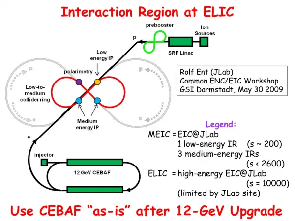
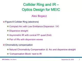
Optics for ELIC - Collider Rings and Interaction Region Design. Alex Bogacz Center for Advanced Studies of Accelerators. ELIC Ring-Ring Collider - Design Choices. ‘Figure-8’ Collider Ring Topology Ensures spin preservation and ease of spin manipulation (spin rotators)

E N D
Optics for ELIC - Collider Rings and Interaction Region Design Alex Bogacz Center for Advanced Studies of Accelerators EIC Collaboration Meeting, Hampton University, May 19-23, 2008
ELIC Ring-Ring Collider - Design Choices • ‘Figure-8’ Collider Ring Topology • Ensures spin preservation and ease of spin manipulation (spin rotators) • Removes spin sensitivity to energy for all ion species • Arc Optics Features • Minimized emittance dilution due to quantum excitations (leptons) • Limited synchrotron radiated power (leptons) • Small momentum compaction to alleviate bunch lengthening (both species) • ‘Aggressive’ Interaction Region (IR) • Vertically crossing rings - ‘crab crossing’ • Ultra small beta Interaction Point (IP) • ‘Dipole second’ IR configuration (D = 0, D’ ≠ 0) EIC Collaboration Meeting, Hampton University, May 19-23, 2008
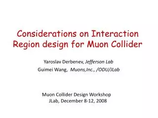
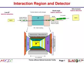
ELIC Interaction Region Challenges • Unprecedented high Luminosity: 7.8×1034 [cm-2 s-1] (peak luminosity per IP) • Enabled by short ion bunches (sz = 5 mm), low beta β* = 5 mm), high rep. rate (1.5 GHz) • ‘Crab Crossing’ required to alleviate luminosity reduction and to avoid parasitic beam-beam interaction due to high repetition rate • Multiple IRs (4) • Chromatic compensation with sextupoles necessary EIC Collaboration Meeting, Hampton University, May 19-23, 2008
Figure-8 Rings -Vertical ‘Stacking’ EIC Collaboration Meeting, Hampton University, May 19-23, 2008
Figure-8 Rings -Vertical ‘Stacking’ EIC Collaboration Meeting, Hampton University, May 19-23, 2008
Figure-8 Rings -Vertical ‘Stacking’ EIC Collaboration Meeting, Hampton University, May 19-23, 2008
150 m 330 m 80 deg Figure-8 Ring with 800 crossing EIC Collaboration Meeting, Hampton University, May 19-23, 2008
Figure-8 Ion Ring (half) - Lattice at 225 GeV 8 empty cells 3 transition cells 8 empty cells 3 transition cells 30 full cells Arc dipoles $Lb=210 cm $B=80.6 kG Arc quadrupoles $Lb=100 cm $G= 7.6 kG/cm phase adv./cell (Dfx= 600, Dfy=600) February 22, 2008
Figure-8 Ion Ring (half) - Lattice at 225 GeV phase adv./cell (Dfx= 600, Dfy=600) 8 empty cells 3 transition cells 8 empty cells 3 transition cells 30 full cells • Minimum dispersion lattice (periodic) • Dispersion suppression via ‘missing’ dipoles (geometrical) • Uniform periodicity of Twiss functions (chromatic cancellations) • Dispersion pattern ‘tailored’ to chromaticity compensation with sextupole families • One family every third cell (3 × 600 = 1800) February 22, 2008
Figure-8 Electron Ring (half) - Lattice at 9 GeV 22 empty cells 22 empty cells 28 superperiods (3 cells/superperiod) Arc dipoles $Lb=300 cm $B=2.7 kG Arc quadrupoles $Lb=30 cm $G= 4.3 kG/cm phase adv./cell (Dfx= 1200, Dfy=1200) February 22, 2008
Figure-8 Electron Ring (half) - Lattice at 9 GeV phase adv./cell (Dfx= 1200, Dfy=1200) 22 empty cells 22 empty cells 28 superperiods (3 cells/superperiod) • Minimized emittance dilution due to quantum excitations (emittance disp. inv. H) • Limited (manageable) synchrotron radiated power Equilibrium Emittance (1200 FODO): Synchrotron Radiated Power: 14.3MW (total) 10.4kW/m @ 1.85A February 22, 2008
Figure-8 Electron Ring (half) - Lattice at 9 GeV phase adv./cell (Dfx= 1200, Dfy=1200) 22 empty cells 22 empty cells 28 superperiods (3 cells/superperiod) Momentum Compaction: • Quasi isochronous arc to alleviate bunch lengthening • Dispersion pattern ‘tailored’ to chromaticity compensation with sextupole families • One family every third quad (3/2 × 1200 = 1800) February 22, 2008
‘straights’ Figure-8 Rings -Vertical ‘Stacking’ EIC Collaboration Meeting, Hampton University, May 19-23, 2008
straight section (330 m) 85 m 85 m 35 m 35 m spin rotator spin rotator e vertical bend vertical bend e 35 m 35 m 0.75 m arc bend arc dipole 20 m i collision point collision point i 0.75 m Vertical crossing angle (22.2 mrad) vertical bend vertical bend spin rotators 35 m 35 m 20 m 35 m 35 m 85 m 85 m 70 m IP FODO Match FF Match FF FODO Chrom Chrom Crab cavity Crab cavity y 7.6 m z Figure-8 Straights with two IPs Note: dimension of the drawing not to scale Minimizing crossing angle reduces crab cavity challenges and required R&D • 85 m free space to accommodate e/p injection/ejection, SRF cavity, electron cooling, and electron polarimeter EIC Collaboration Meeting, Hampton University, May 19-23, 2008
IR design with ’interleaved’ FF quads 0.2m 0.5m 3.2kG/cm 22.2 mrad 1.27 deg 3.8m 0.6m 2.55kG/cm 8.4cm 10cm IP 1.8m 20.8kG/cm 3m 12KG/cm 22.9cm Vertical intercept Vertical intercept 16.2cm 14.4cm 4.5m Vertical intercept electron 4mm 5mm ion EIC Collaboration Meeting, Hampton University, May 19-23, 2008
‘Lambertson quad’ for the final focus Electron (9GeV) 2.4cm 2.4cm 8.6cm 14cm 4.6cm 10 cm 10cm 4.8cm 3cm Proton (225GeV) 3cm 1.8m 20.8kG/cm B-Field in coil and force collar following talk by Paul Brindza EIC Collaboration Meeting, Hampton University, May 19-23, 2008
‘Crab Crossing’ - Multi-cell SRF cavities K. Oide Crab Cavity requirement for 22 mrad crossing: Electron: 1.2 MV – (KEK, single cell, 1.4 MV) Ion: 24 MV(multi-cell cavity, R&D raquired) KEK B-Factory ‘Crab Cavity’ - Squashed cell cavity @ TM110 B field EIC Collaboration Meeting, Hampton University, May 19-23, 2008
Final Focus Optics - Beam envelopes Eelectron = 9 GeV b* = 5/5 mm eN = 90/3.6 mm rad bmax = 3.1/32 km smax = 4.0/2.4 mm Quads L[cm] G[kG/cm] 50 3.2 60 -2.6 80 3.9 803.9 350 cm 350 cm 380 cm 220 cm 100 cm 380 cm 220 cm 100 cm Eion = 225 GeV b* = 5/5 mm eN = 1.3/0.06 mm rad smax = 5.0/3.8 mm bmax = 4.8/54 km Quads L[cm] G[kG/cm] 180 20.8 300 -12.0 200 23.0 200 -22.0 350 cm 350 cm 450 cm 450 cm 100 cm 100 cm 50 cm 50 cm EIC Collaboration Meeting, Hampton University, May 19-23, 2008
IR - Matching to the Ring Eele = 9 GeV bx,ymax = 3.1/32 km bx,y* = 5 mm 3.8 m FF doublet FF doublet matching singlet-doublet FODO EIC Collaboration Meeting, Hampton University, May 19-23, 2008
IR - Matching to the Ring Eele = 9 GeV bx,ymax = 3.1/32 km bx,y* = 5 mm 3.8 m FF doublet FF doublet matching singlet-doublet FODO EIC Collaboration Meeting, Hampton University, May 19-23, 2008
IR - Matching to the Ring Eele = 9 GeV bx,ymax = 3.1/32 km bx,y* = 5 mm 3.8 m FF doublet FF doublet matching singlet-doublet FODO EIC Collaboration Meeting, Hampton University, May 19-23, 2008
IR - Matching to the Ring Eele = 9 GeV bx,ymax = 3.1/32 km bx,y* = 5 mm 3.8 m FF doublet FF doublet matching singlet-doublet FODO EIC Collaboration Meeting, Hampton University, May 19-23, 2008
IR Beta Chromaticity IR Ions IR elactrons Dp/p = 0, 0.0001,….., 0.0005 following talk by Hisham Sayed EIC Collaboration Meeting, Hampton University, May 19-23, 2008
‘Spin rotators’ - Electron Ring at 9 GeV empty ‘straight’ cells full ‘bending’ cells Solenoid magnet $Lb=300 cm $B=100 kG following talk by Pavel Chevtsov EIC Collaboration Meeting, Hampton University, May 19-23, 2008
‘Spin rotators’ - Electron Ring at 9 GeV empty ‘straight’ cells full ‘bending’ cells Skew Quads $Lb=90 cm $G=0.18 kG/cm decoupled spin rotator module EIC Collaboration Meeting, Hampton University, May 19-23, 2008
Conclusions • Compelling case for High Luminosity ELIC • Based on present assumptions 1035 [cm-2 s-1] luminosity collider is feasible … more studies needed… • Optics - Conceptual lattice design of major sub-systems • Interleaved Interaction Regions for both species • Figure-8 Arc lattices • Matching between sections • Compact ‘Spin rotator’ Optics • Still to come…. • Chromatic compensations, higher order effects • Complete spin matching Optics (IR-to-IR) EIC Collaboration Meeting, Hampton University, May 19-23, 2008