Download
1 / 21
210 likes | 335 Views
8644-T7B. ISUAL DPU-to-DCM Interface and Protocol. Rev Description Date A Initial release 20-Feb-2001 SG B MMCB Format changes, List in MM 12-Apr-2001 SG.

E N D
8644-T7B ISUAL DPU-to-DCMInterface and Protocol Rev Description Date A Initial release 20-Feb-2001 SG B MMCB Format changes, List in MM 12-Apr-2001 SG 8644-T7B - DCM Software Interface
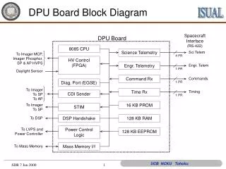
Overview of DPU-DCM Protocol • DPU turns on DCM . • DCM activates Busy until initialization is complete; it then goes Idle (deactivates Busy). • When DPU has data ready, and DCM is not Busy, it activates the DCM with the ATN signal. • DCM activates Busy until compressions are complete; it then goes Idle. 8644-T7B - DCM Software Interface
DCM Program • DCM starts with a ROM program. • DPU copies the compression software into Mass Memory (MM). This is called the Program Logic Block (PLB) • DPU sends CDI commands to tell DCM where the PLB is located. 8644-T7B - DCM Software Interface
CDI Commands • CDI commands to set the address of the initial MMCB: • operation=34 hex data=high 2 bytes of address • operation=35 hex data=low 2 bytes of address • CDI commands to set the address of the PLB area: • operation=36 hex data=high 2 bytes of address • operation=37 hex data=low 2 bytes of address • The DPU will send commands in the order 34, 35, 36, 37. 8644-T7B - DCM Software Interface
Layout of PLB Area • 4 bytes - number of bytes (N) in DSP program • 1 byte - checksum of DSP program (covering N bytes) • N bytes - the DSP program (up to 256K bytes) • Number of bytes is stored high-byte-first • (example: decimal 123456 is stored hex 00 01 E2 40) • This convention is used for all number storage. • The PLB checksum is the exclusive-OR of all N bytes in the DSP program. 8644-T7B - DCM Software Interface
How the DCM gets data to compress • There is a list of 16 Mass Memory Control Blocks (MMCB), written in to MM by the DPU. • MMCBs specify where the data is within MM. • DCM does up to 16 compression “jobs” at a time, one for each MMCB 8644-T7B - DCM Software Interface
Mass Memory Control Block(MMCB) • Used to allocate memory for instrument buffer readouts. • MMCBs are stored in DPU extended RAM, structured as queues -- linked lists. (DCM does not see these queues.) • DCM receives a list of copies of MMCBs, each with a checksum, stored in MM 8644-T7B - DCM Software Interface
MMCB Compression List • The list of MMCB copies in MM is called the “Compression List” • The address of the first MMCB in the list is set by CDI commands. • There are 16 MMCBs in the Compression List. 8644-T7B - DCM Software Interface
How the DCM uses the Compression List • The DCM software processes each MMCB in the list. • If the checksum fails, it goes to next MMCB • Otherwise, it compresses the data, and goes to the next MMCB • After processing the last MMCB, the DCM goes Idle, waiting for an ATN signal. 8644-T7B - DCM Software Interface
MMCB Layout • [offset 0, 1 byte] Status: • 0=no operation required • 1=readout complete, ready to compress • 2=compression complete • [offset 1, 1 byte] Input Data type: • 0=Camera - Aurora • 1=Spectrophotometer • 2=Slow-Rate Spectrophotometer • 3=Array Photometer 8644-T7B - DCM Software Interface
MMCB Layout • [offset 2, 1 byte] mmcb_mode -Science Mode • 1=Aurora • 2=Sprite Continuous • 3=Sprite Burst • [offset 3, 4 bytes] mmcb_OI • Pointer to Original Input raw data in MM • [offset 7, 4 bytes] mmcb_OI_n • Number of OI bytes allocated 8644-T7B - DCM Software Interface
MMCB Layout • [offset 11, 6 bytes] (not used by DCM) • [offset 17, 6 bytes] (not used by DCM) • [offset 23, 2 bytes] mmcb_ns • Number of images or samples • [offset 25, 1 byte] mmcb_E3 • DCM ‘E3’ status byte 8644-T7B - DCM Software Interface
MMCB Layout • [offset 26, 4 bytes] mmcb_obytes • number of compressed bytes stored by the DCM • [offset 30, 1 byte] mmcb_ochk • checksum of compressed output (XOR of all bytes) 8644-T7B - DCM Software Interface
MMCB Layout • [offset 31, 3 bytes] (not used by DCM) • [offset 34, 1 byte] (not used by DCM) • [offset 35, 1 byte] mmcb_checksum • Checksum of MMCB (XOR of previous 35 bytes) 8644-T7B - DCM Software Interface
Notes • Compressed Data will over-write the original information. • DCM will compute a checksum of the compressed data, and a separate checksum of the updated MMCB • First byte(s) of compressed data will tell the ground-based decompression software which algorithm to use 8644-T7B - DCM Software Interface
Initialization by the DPU • Turn on DCM • Verify that Busy went active • Wait for Busy to go inactive • Send CDI commands giving addresses of PLB and MMCB List • Verify that Busy went active • Wait for Busy to go inactive 8644-T7B - DCM Software Interface
After Initialization • DCM is “idle”, waiting for ATN • (it does not start processing MMCBs) 8644-T7B - DCM Software Interface
DPU Normal Operation • Accumulate up to 16 MMCBs, write them into MM Compression List • Signal DCM with ATN • Verify that Busy went active • Wait for Busy to go inactive • Process compressed data into TM • Repeat 8644-T7B - DCM Software Interface
Camera Data • Camera data will be an array of images. • Number of columns = 512 • Number of rows = 128 • Number of images: • 1 or more in Aurora mode • 8 in Burst mode • typically 6 in Continuous mode 8644-T7B - DCM Software Interface
Photometer Data • In Sprite modes, data is delivered as arrays of samples. • Size of array given in MMCB 8644-T7B - DCM Software Interface
END 8644-T7B - DCM Software Interface