Download
1 / 70
710 likes | 876 Views
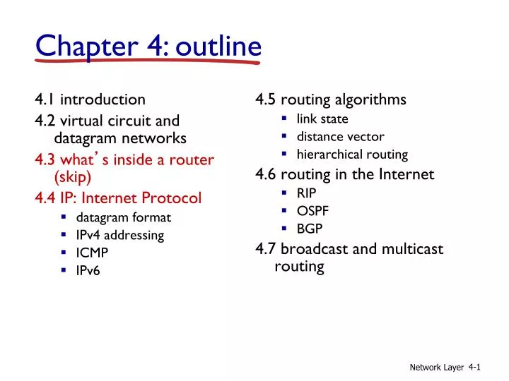
4.1 introduction 4.2 virtual circuit and datagram networks 4.3 what ’ s inside a router (skip) 4.4 IP: Internet Protocol datagram format IPv4 addressing ICMP IPv6. 4.5 routing algorithms link state distance vector hierarchical routing 4.6 routing in the Internet RIP OSPF BGP

E N D
4.1 introduction 4.2 virtual circuit and datagram networks 4.3 what’s inside a router(skip) 4.4 IP: Internet Protocol datagram format IPv4 addressing ICMP IPv6 4.5 routing algorithms link state distance vector hierarchical routing 4.6 routing in the Internet RIP OSPF BGP 4.7 broadcast and multicast routing Chapter 4: outline Network Layer
host, router network layer functions: • IP protocol • addressing conventions • datagram format • packet handling conventions forwarding table The Internet network layer transport layer: TCP, UDP • routing protocols • path selection • RIP, OSPF, BGP network layer • ICMP protocol • error reporting • router “signaling” link layer physical layer Network Layer
IP protocol version number 32 bits total datagram length (bytes) header length (bytes) type of service head. len ver length for fragmentation/ reassembly fragment offset “type” of data flgs 16-bit identifier max number remaining hops (decremented at each router) upper layer time to live header checksum 32 bit source IP address 32 bit destination IP address upper layer protocol to deliver payload to e.g. timestamp, record route taken, specify list of routers to visit. options (if any) data (variable length, typically a TCP or UDP segment) IP datagram format how much overhead? • 20 bytes of TCP • 20 bytes of IP • = 40 bytes + app layer overhead Network Layer
IP datagram format Network Layer
Link MTU vs. Path MTU vs. MSS • Maximum Transmission Unit (MTU) is defined by the maximum payload size of the Layer 2 frame. • Link MTU: The max packet size that can be transmitted over a link • Path MTU: The minimum link MTU of all links in a path between a source and a destination • Layer 3 payload determines Layer 4 Maximum Segment Size(MSS) MAC Header TransportLayer (Path MTU)
network links have MTU - largest possible link-level frame different link types, different MTUs large IP datagram divided (“fragmented”) within net one datagram becomes several datagrams “reassembled” only at final destination IP header bits used to identify, order related fragments … … reassembly IP fragmentation, reassembly fragmentation: in: one large datagram out: 3 smaller datagrams Network Layer
length =1040 length =4000 length =1500 length =1500 ID =x ID =x ID =x ID =x fragflags =000 fragflags =001 fragflags =001 fragflags =010 offset =370 offset =185 offset =0 offset =0 one large datagram becomes several smaller datagrams IP fragmentation, reassembly example: • 4000 byte datagram • MTU = 1500 bytes 1480 bytes in data field (20 bytes in head) offset = 1480/8 offset = 2960/8 Network Layer
4.1 introduction 4.2 virtual circuit and datagram networks 4.3 what’s inside a router 4.4 IP: Internet Protocol datagram format IPv4 addressing ICMP IPv6 4.5 routing algorithms link state distance vector hierarchical routing 4.6 routing in the Internet RIP OSPF BGP 4.7 broadcast and multicast routing Chapter 4: outline Network Layer
IP address: 32-bit identifier for host, router interface interface: connection between host/router and physical link router’s typically have multiple interfaces host typically has one or two interfaces (e.g., wired Ethernet, wireless 802.11) IP addresses associated with each interface 223.1.1.2 223.1.3.27 IP addressing: introduction 223.1.1.1 223.1.2.1 223.1.1.4 223.1.2.9 223.1.1.3 223.1.2.2 223.1.3.2 223.1.3.1 223.1.1.1 = 11011111 00000001 00000001 00000001 223 1 1 1 Network Layer
Q: how are interfaces actually connected? A: we’ll learn about that in chapter 5, 6. 223.1.1.2 223.1.3.27 IP addressing: introduction 223.1.1.1 223.1.2.1 223.1.1.4 223.1.2.9 223.1.1.3 223.1.2.2 A: wired Ethernet interfaces connected by Ethernet switches (or hubs) 223.1.3.2 223.1.3.1 For now: don’t need to worry about how one interface is connected to another (with no intervening router) A: wireless WiFi interfaces connected by WiFi base station Network Layer
IP address: subnet part - high order bits host part - low order bits what’s a subnet ? device interfaces with same subnet part of IP address can physically reach each other without intervening router subnet Subnets 223.1.1.1 223.1.2.1 223.1.1.2 223.1.1.4 223.1.2.9 223.1.2.2 223.1.3.27 223.1.1.3 223.1.3.2 223.1.3.1 network consisting of 3 subnets Network Layer
recipe to determine the subnets, detach each interface from its host or router, creating islands of isolated networks each isolated network is called a subnet 223.1.1.0/24 223.1.2.0/24 223.1.1.1 223.1.2.1 223.1.1.2 223.1.1.4 223.1.2.9 223.1.2.2 223.1.3.27 223.1.1.3 223.1.3.2 223.1.3.1 223.1.3.0/24 subnet Subnets subnet mask: /24 Network Layer
how many? Subnets 223.1.1.2 223.1.1.1 223.1.1.4 223.1.1.3 223.1.7.0 223.1.9.2 223.1.9.1 223.1.7.1 223.1.8.1 223.1.8.0 223.1.2.6 223.1.3.27 223.1.2.1 223.1.2.2 223.1.3.1 223.1.3.2 Network Layer
Classful Addressing 0~127 128~191 192~223 224~239 240~255 Network Layer
Classful Addressing Class A, B and C addresses are divided into 2 parts: (fixed sized) Netid and Hostid. Network Layer
Classful Addressing – blocks in class A Class A addresses are wasted!!! Network Layer
Classful Addressing – blocks in class A Many class B addresses are wasted too. Network Layer
Classful Addressing – blocks in class A Class C blocks are too small for most businesses. Network Layer
Masking Concept Given an address from a block of addresses, we can find the network address (netid) by ANDing with a mask. Network Layer
Masking Concept - Default masks - Network address (netid) can be found by applying the default mask to any of the addresses in the block (including itself). - The masked address retains the netid of the block and sets the hostid to zero. Network Layer
IP addressing: CIDR CIDR:Classless InterDomain Routing • subnet portion of address of “arbitrary length” • address format: a.b.c.d/x, where x is # bits in subnet portion of address host part subnet part 11001000 00010111 00010000 00000000 200.23.16.0/23 Network Layer
IP addressing: CIDR Subnet mask • Used by every machine to determine which part of IP address is to be used for the “subnet address” 255.255.255.128 /25 255.255.255.192 /26 . . . 255.255.255.254 /31 Network Layer
IP addresses: how to get one? Q: How does a host get IP address? • hard-coded by system admin in a file • Windows: control-panel->network->configuration->tcp/ip->properties • UNIX: /etc/rc.config • DHCP:Dynamic Host Configuration Protocol: dynamically get address from as server • “plug-and-play” Network Layer
DHCP: Dynamic Host Configuration Protocol goal: allow host to dynamically obtain its IP address from network server when it joins network • can renew its lease on address in use • allows reuse of addresses (only hold address while connected/“on”) • support for mobile users who want to join network (more shortly) DHCP overview: • host broadcasts “DHCP discover” msg [optional] • DHCP server responds with “DHCP offer” msg [optional] • host requests IP address: “DHCP request” msg • DHCP server sends address: “DHCP ack” msg Network Layer
DHCP client-server scenario DHCP server 223.1.1.0/24 223.1.2.1 223.1.1.1 223.1.1.2 arriving DHCP client needs address in this network 223.1.1.4 223.1.2.9 223.1.2.2 223.1.3.27 223.1.1.3 223.1.2.0/24 223.1.3.2 223.1.3.1 223.1.3.0/24 Network Layer
DHCP discover src : 0.0.0.0, 68 dest.: 255.255.255.255,67 yiaddr: 0.0.0.0 transaction ID: 654 DHCP client-server scenario DHCP server: 223.1.2.5 arriving client DHCP offer src: 223.1.2.5, 67 dest: 255.255.255.255, 68 yiaddr: 223.1.2.4 transaction ID: 654 lifetime: 3600 secs DHCP request src: 0.0.0.0, 68 dest:: 255.255.255.255, 67 yiaddr: 223.1.2.4 transaction ID: 655 lifetime: 3600 secs yiaddr = Your IP Address DHCP ACK src: 223.1.2.5, 67 dest: 255.255.255.255, 68 yiaddr: 223.1.2.4 transaction ID: 655 lifetime: 3600 secs Network Layer
DHCP: more than IP addresses DHCP can return more than just allocated IP address on subnet: • address of first-hop router for client • name and IP address of DNS sever • network mask (indicating “network portion” versus host portion of address) Network Layer
DHCP UDP IP Eth Phy DHCP UDP IP Eth Phy DHCP DHCP DHCP DHCP DHCP DHCP DHCP DHCP DHCP DHCP DHCP: example • connecting laptop needs its IP address, addr of first-hop router, addr of DNS server: use DHCP • DHCP request encapsulated in UDP, encapsulated in IP, encapsulated in 802.1 Ethernet 168.1.1.1 • Ethernet frame broadcast (dest: FFFFFFFFFFFF) on LAN, received at router running DHCP server router with DHCP server built into router • Ethernet demuxed to IP demuxed, UDP demuxed to DHCP Network Layer
DHCP UDP IP Eth Phy DHCP UDP IP Eth Phy DHCP DHCP DHCP DHCP DHCP DHCP DHCP DHCP DHCP DHCP: example • DCP server formulates DHCP ACK containing client’s IP address, IP address of first-hop router for client, name & IP address of DNS server • encapsulation of DHCP server, frame forwarded to client, demuxing up to DHCP at client router with DHCP server built into router • client now knows its IP address, name and IP address of DSN server, IP address of its first-hop router Network Layer
IP addresses: how to get one? Q: how does (sub)network get subnet part of IP addr? A: a (sub)network is allocated “portion of its provider ISP’s address space” Subnetting ISP's block 11001000 00010111 00010000 00000000 200.23.16.0/20 Organization 0 11001000 00010111 00010000 00000000 200.23.16.0/23 Organization 1 11001000 00010111 00010010 00000000 200.23.18.0/23 Organization 2 11001000 00010111 00010100 00000000 200.23.20.0/23 ... ….. …. …. Organization 7 11001000 00010111 00011110 00000000 200.23.30.0/23 Network Layer
Subnetting IP addresses are designed with two levels of hierarchy: A netid and a host id. This network (141.14.0.0) is a class B and can have 2^16 hosts. There is only 1 network with a whole-lotta hosts! Network Layer
Subnetting What if we break the network into 4 subnets? Network Layer
Subnetting Network Layer
Subnetting Most ISP use “subnetting” Allocate its address block into each sub group (organization) ISP's block 11001000 00010111 00010000 00000000 200.23.16.0/20 Organization 0 11001000 00010111 00010000 00000000 200.23.16.0/23 Organization 1 11001000 00010111 00010010 00000000 200.23.18.0/23 Organization 2 11001000 00010111 00010100 00000000 200.23.20.0/23 ... ….. …. …. Organization 7 11001000 00010111 00011110 00000000 200.23.30.0/23 Network Layer
Subnetting - netmask Network Layer
Subnetting - netmask • What is the subnetwork address if the address is 200.45.34.56 and the subnet mask is 255.255.240.0? • We apply the AND operation on the address and the subnet mask. Address ➡ 11001000 00101101 00100010 00111000 Subnet Mask ➡ 11111111 11111111 11110000 00000000 Subnetwork Address ➡ 11001000 00101101 00100000 00000000. Or, 200.45.32.0 Network Layer
KoreaTech Subnetting KoreaTech is allocated the network address “220.68.64.0/19” Allocate its address block into each sub group 220 68 ISP's block 11011100 1000100 01000000 00000000 220.68.64.0/19 Organization 1 11011100 1000100 01000000 00000000 220.68.64.0/24 Organization 2 11011100 1000100 01000001 00000000 220.68.65.0/24 Organization 3 11011100 1000100 01000010 00000000 220.68.66.0/24 ... ….. …. …. Organization 32 11011100 1000100 01011111 00000000 220.68.95.0/24 Network Layer
200.23.16.0/23 200.23.18.0/23 200.23.30.0/23 200.23.20.0/23 . . . . . . Hierarchical addressing: route aggregation hierarchical addressing allows efficient advertisement of routing information: Organization 0 Organization 1 “Send me anything with addresses beginning 200.23.16.0/20” Organization 2 Fly-By-Night-ISP Internet Organization 7 “Send me anything with addresses beginning 199.31.0.0/16” ISPs-R-Us Network Layer
200.23.16.0/23 200.23.18.0/23 200.23.30.0/23 200.23.20.0/23 . . . . . . Hierarchical addressing: more specific routes ISPs-R-Us has a more specific route to Organization 1 Organization 0 “Send me anything with addresses beginning 200.23.16.0/20” Organization 2 Fly-By-Night-ISP Internet Organization 7 “Send me anything with addresses beginning 199.31.0.0/16 or 200.23.18.0/23” ISPs-R-Us Organization 1 Network Layer
IP addressing: the last word... Q: how does an ISP get block of addresses? A:ICANN: Internet Corporation for Assigned Names and Numbers http://www.icann.org/ • allocates addresses • manages DNS • assigns domain names, resolves disputes Network Layer
IP addressing: the last word... • ICANN 산하 IANA (Internet Assigned Numbers Authority) • 인터넷 할당 번호 관리기관 • RIR (Regional Internet Registry) • 대륙별인터넷 레지스트리 • APNIC (Asia Pacific Network Information Center) • 아시아· 태평양 지역 • RIPE-NCC (Réseaux IP Européens Network Co-ordination Centre) • 유럽 • ARIN (American Registry for Internet Number) • 북남미 외 기타 지역 • 국가별 NIC (Network Information Center) • 한국은 KISA(한국인터넷진흥원) 안에 KRNIC(한국인터넷정보센터) 에서 담당 • https://ip.kisa.or.kr/main.html Network Layer
NAT: network address translation rest of Internet local network (e.g., home network) 10.0.0/24 10.0.0.1 10.0.0.4 10.0.0.2 138.76.29.7 10.0.0.3 datagrams with source or destination in this network have 10.0.0/24 address for source, destination (as usual) alldatagrams leaving local network have same single source NAT IP address: 138.76.29.7,different source port numbers Network Layer
NAT: network address translation Addresses for private networks Network Layer
NAT: network address translation motivation: local network uses just one IP address as far as outside world is concerned: • range of addresses not needed from ISP: just one IP address for all devices • can change addresses of devices in local network without notifying outside world • can change ISP without changing addresses of devices in local network • devices inside local net not explicitly addressable, visible by outside world (a security plus) Network Layer
NAT: network address translation implementation: NAT router must: • outgoing datagrams:replace (source IP address, port #) of every outgoing datagram to (NAT IP address, new port #) . . . remote clients/servers will respond using (NAT IP address, new port #) as destination addr • remember (in NAT translation table)every (source IP address, port #) to (NAT IP address, new port #) translation pair • incoming datagrams:replace (NAT IP address, new port #) in dest fields of every incoming datagram with corresponding (source IP address, port #) stored in NAT table Network Layer
3 1 2 4 S: 10.0.0.1, 3345 D: 128.119.40.186, 80 S: 138.76.29.7, 5001 D: 128.119.40.186, 80 1:host 10.0.0.1 sends datagram to 128.119.40.186, 80 2:NAT router changes datagram source addr from 10.0.0.1, 3345 to 138.76.29.7, 5001, updates table S: 128.119.40.186, 80 D: 10.0.0.1, 3345 S: 128.119.40.186, 80 D: 138.76.29.7, 5001 NAT: network address translation NAT translation table WAN side addr LAN side addr 138.76.29.7, 5001 10.0.0.1, 3345 …… …… 10.0.0.1 10.0.0.4 10.0.0.2 138.76.29.7 10.0.0.3 4:NAT router changes datagram dest addr from 138.76.29.7, 5001 to 10.0.0.1, 3345 3:reply arrives dest. address: 138.76.29.7, 5001 Network Layer
NAT: network address translation • 16-bit port-number field: • 60,000 simultaneous connections with a single LAN-side address! • NAT is controversial: • routers should only process up to layer 3 • violates end-to-end argument • NAT possibility must be taken into account by app designers, e.g., P2P applications • address shortage should instead be solved by IPv6 Network Layer
NAT traversal problem Network Layer
NAT traversal problem • client wants to connect to server with address 10.0.0.1 • server address 10.0.0.1 local to LAN (client can’t use it as destination addr) • only one externally visible NATed address: 138.76.29.7 • solution1: statically configure NAT to forward incoming connection requests at given port to server • e.g., (123.76.29.7, port 21) always forwarded to 10.0.0.1 port 21 10.0.0.1 client ? 10.0.0.4 138.76.29.7 NAT router Network Layer
10.0.0.1 IGD NAT router NAT traversal problem NAT translation table WAN side addr LAN side addr • solution 2: Universal Plug and Play (UPnP)-Internet Gateway Device (IGD) Protocol. Allows NATed host to: • learn public IP address (138.76.29.7) • add/remove port mappings (with lease times) i.e., automate static NAT port map configuration 138.76.29.7, 80 10.0.0.1, 80 …… …… Network Layer