Download
1 / 21
290 likes | 736 Views
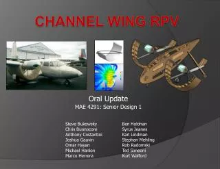
Delta-Wing Vortex Lift Enhancement Using Oblique Channel Distribution. Advisor: Dr. McClain Project Manager: Meag McNary Ruben Nunez Adam Eaker Ryan Parker Drew Waggoner. ME LAB 4335- Final Presentation. Overview. Initial Objective Final Objective Theory Experimentation

E N D
Delta-Wing Vortex Lift Enhancement Using Oblique Channel Distribution Advisor: Dr. McClain Project Manager: MeagMcNary Ruben Nunez Adam Eaker Ryan Parker Drew Waggoner ME LAB 4335- Final Presentation
Overview • Initial Objective • Final Objective • Theory • Experimentation • Schedule Summary • Results • Significance • Summary • Recommendations • Questions
Initial Objective • Quantify the steady flow effects of oblique element distributions interacting with vortical structures attached to a delta wing micro unmanned air vehicle Areas of interest: • High angle of attack • Roughness elements • Lift and Drag
Final Objective • Quantify the steady flow effects of obliquely aligned channels interacting with vortical structures on a delta wing micro unmanned air vehicle Areas of interest: • High angles of attack • Low Reynolds Numbers • Obliquely aligned channels • Lift and Drag
Theory – Vortex Behavior • Unpredictable behavior • Leading-edge vortices • Induces additional lift by pressure decrease on suction surface • Vortex breakdown • Vortex expands into highly fluctuating structure • Induced by high angles of attack or pressure rise • Vortex separates from wing • Disadvantages: • Wing fluttering • Loss of performance • Decrease in lift Vortex Breakdown
Theory – Vortex Breakdown Control • Delay bursting of vortices • Increases performance • Controlled by increasing ωθand induce secondary flow • Methods: • Mechanical • Local action by contouring surface • Pneumatic • Introduce perturbations through air flow VL Vθ Obliquely aligned elements Vortex separation line reattachment line Leading-edge separation line Control element region
Jet Flaps • Leading or Trailing edge • Can be difficult to implement. • Leading edge: + large increase on lift, - large increase on drag. • Trailing edge: + increase stability - small increase on lift,
Piezoelectric Strips • Bonded on delta wing for active control of oscillations. • Serve as sensors and actuators. • Voltages applied across strips create forces to counter oscillations. • Lightweight, cheap, and easy to manufacture.
Obliquely Aligned Elements • Elements prevent breakdown of vortices by directing air flow and produce high lift forces. • Elements also prevent buffeting and oscillations. • Moderate drag penalty. Vortex separation line reattachment line Leading-edge separation line Control element region
Obliquely Aligned Channels • Designed to stabilize the vortical flow. • Restrict pressure rises that precipitate breakdown. • Increase ωθand induce secondary flow • Promote Reattatchment
Experimentation • Set up to determine the lift and drag coefficients on a Delta Wing with varying angles of attack • Measurements: • Data Acquisition • LABVIEW • Angle of Attack (0° to 45°) • Using a set screw to adjust attack angle in 5° increments • Lift and Drag Force • Force Balance • Static Pressure Difference • Using a Pitot-Static Tube and the PCL2A WIND TUNNEL Test Section Wind Direction Delta Wing Figure 1: Wind tunnel experiment set-up to determine lift and drag coefficients on a Delta Wing with a fixed wind velocity.
Results • Overall trend is the same for both wings • Lift and drag are less in the channeled • Increased difference in lift just before stall • Stall occurred at approximately 35° • Lift after stall was greater for the channeled
Significance • Oblique channels do not increase performance • The effects after stall might suggest improvement is possible
Summary • There are multiple ways to manipulate the vortical breakdown • Mechanical • Pneumatic • Channeled wing does not drastically increase performance • Lift force reduced • Drag force reduced
Recommendations • Improvements in the channeled design might allow for better performance than current model • Test at higher Reynolds numbers • Resume original test criteria • Oblique elemental distributions • Arrangement of the distributions